Overflow valve

An overflow valve and overflow technology, which is applied in the field of sanitary ware, can solve the problems of reducing drainage speed, etc., and achieve the effects of improving overflow capacity, reducing noise, and simple structure

Pending Publication Date: 2020-08-04
GULI (XIAMEN) TECH CO LTD
View PDF0 Cites 1 Cited by
  • Summary
  • Abstract
  • Description
  • Claims
  • Application Information

AI Technical Summary

Problems solved by technology

When the drain valve is opened, the water flows out through the drain port of the drain valve base. During normal use, since the drain port of the drain valve base communicates with the outside air through the overflow pipe channel, when draining, a negative pressure will be generated in the drain channel, and the outside world will Under the action of atmospheric pressure, the air will be mixed into the drain outlet of the drain valve base, so that the drain channel is not full of water, thereby reducing the draining speed

Method used


Image

  • Overflow valve
  • Overflow valve
  • Overflow valve

Examples


Embodiment 1

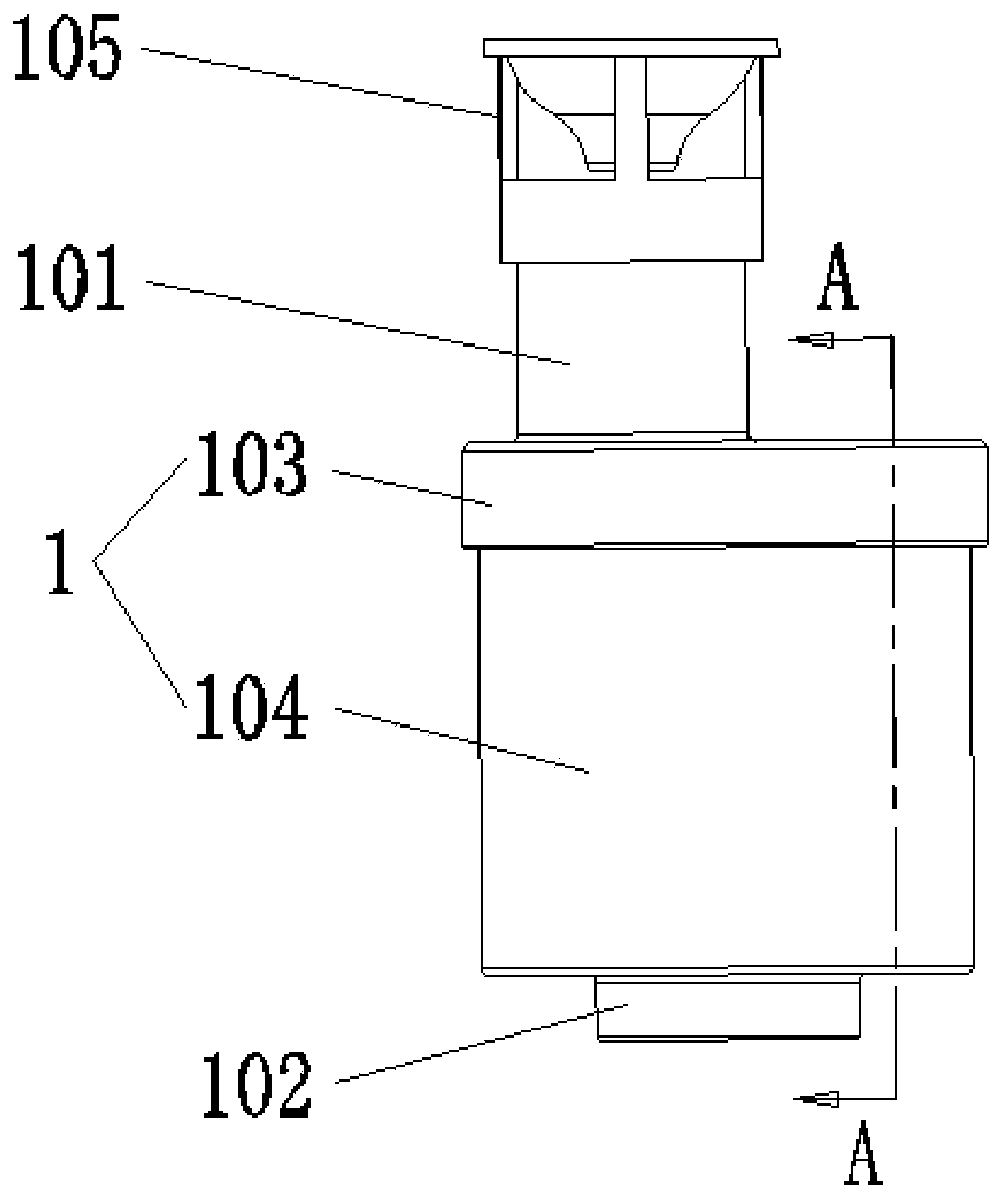
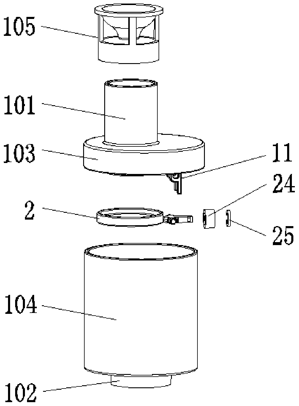
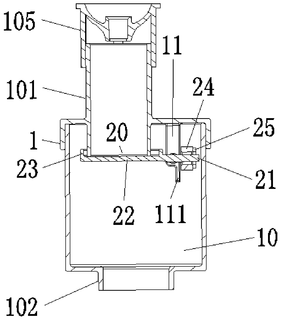
[0041] Such as Figure 1-6 As shown, an overflow valve includes a housing 1 and a swing lever assembly. A water guide chamber 10 is opened inside the housing 1. The top and bottom of the housing 1 are respectively provided with a water inlet pipe 101 and a The drain pipe 102 and the bottom of the water inlet pipe 101 extend into the water guiding cavity 10 . A support is fixed on the top of the water guide chamber 10 at the side of the water inlet pipe 101 . The support includes two support plates 11 arranged in parallel and spaced apart from each other. The support plates 11 are provided with positioning holes 110 .

[0042] The swing lever assembly 2 includes a lever guide column 21 whose middle part is hinged to the bottom of the support, a water seal structure fixed at one end of the lever guide column 21 close to the water inlet pipe 101, and a water seal structure fixed at the other end of the lever guide column 21 and used for sealing with the water. The structure form...

Embodiment 2

[0052] Such as Figure 14-16 As shown, the difference between this embodiment and Embodiment 1 is that the load is a spring 26, and the top wall of the water guide chamber 10 is fixedly provided with a connecting rod 12 on the side of the support, and the lower part of the connecting rod 12 is lower than the lever guide post. 21 A horizontal plate 13 is fixed on the position of the hinged fulcrum, the lower end of the spring 26 is fixed on the horizontal plate 13, and the upper end is connected with the bottom of the lever guide column 21 and is in a stretched state. The rest of the structure of this embodiment is the same as that of Embodiment 1.

[0053] Such as Figure 17 As shown, under normal circumstances, the lever guide post 21 is due to the pulling force of the spring 26, the moment M1 produced by the spring 26 is greater than the moment M2 at the other end of the lever guide post 21, and the lever guide post 21 is in a closed state ( Figure 17 a); when the water s...


PUM


Abstract

The invention discloses an overflow valve. The overflow valve comprises a shell and a swing lever assembly, a water guide cavity is formed in the shell, a water inlet pipe and a water outlet pipe arearranged at the top and the bottom of the shell respectively, the bottom of the water inlet pipe extends into the water guide cavity, and a supporting piece is fixedly arranged on the side of the water inlet pipe. The swing lever assembly comprises a lever guide column hinged to the lower portion of the supporting piece, a water seal structure fixedly arranged at one end of the lever guide columnand a load fixedly arranged at the other end of the lever guide column. The water seal structure comprises a partition plate and an annular water baffle, a water storage area is defined by the annularwater baffle and the partition plate, and the bottom of the water inlet pipe extends into the water storage area. Under the normal condition, the swing lever assembly is in a closed state under the balance effect of the load, water in the water storage area plays a role in isolating air, when a drain valve drains water, outside air cannot enter a water outlet from the water inlet pipe, and the drainage speed is greatly increased through the siphonic effect; and when the pressure borne by the water seal structure is larger than the acting force of the load, the lever guide column rotates and opens the water inlet pipe to achieve overflowing.

Description

technical field [0001] The invention relates to the field of bathroom, in particular to an overflow valve. Background technique [0002] Existing drain valve is made of valve body, base, overflow pipe. Wherein, the valve base communicates with the overflow pipe. Under the normal water-stop state, the outside air communicates with the drain port of the drain valve base through the overflow pipe. When an overflow occurs, water flows from the overflow pipe to the drain at the base of the drain valve and into the toilet pipe. When the drain valve is opened, the water flows out through the drain port of the drain valve base. During normal use, since the drain port of the drain valve base communicates with the outside air through the overflow pipe channel, when draining, a negative pressure will be generated in the drain channel, and the outside world will Under the action of atmospheric pressure, air will be mixed into the drain outlet of the drain valve base together, so that...

Claims


Application Information

Patent Timeline
Patent Type & Authority Applications(China)
IPC IPC(8): F16K17/04F16K17/12E03D1/34
CPCE03D1/34F16K17/0413F16K17/12
Inventor 陈雪瑜
Owner GULI (XIAMEN) TECH CO LTD
Why Eureka
Try Eureka