Electronic detonator leg wire tail end connecting device and electronic detonator

An electronic detonator and connecting device technology, which is applied to weapon accessories, fuzes, offensive equipment, etc., can solve problems such as the inability to achieve the set blasting shape and directional blasting, the inability to achieve the blasting shape, the blasting directional target, and the unreliable connection. , to maintain integrity and stability, good waterproof and rainproof functions, and ensure accurate and controllable effects

Pending Publication Date: 2020-08-04
谢正怀
View PDF9 Cites 0 Cited by
  • Summary
  • Abstract
  • Description
  • Claims
  • Application Information

AI Technical Summary

Problems solved by technology

like figure 1 As shown, in the current electronic detonator blasting system, the tail wires of each electronic detonator are connected in parallel to the detonating bus, and the connection and installation are completed through junction boxes. Usually, several junction boxes are clamped on the detonating bus, and The detonating busbars are all metal wires such as copper core wires. During installation, the skin needs to be peeled off manually to ensure that the cutter touches the copper core wires, and then the detonator and the detonating busbars are wound together. If the exposed wires are in contact with the ground or in rainy weather, it will easily cause excessive network resistance or short circuit, which will affect the detonation network, and it is time-consuming and labor-intensive to connect multiple groups of detonator legs to the detonation bus, which greatly reduces work efficiency
[0003] In order to achieve the shape of the set blasting and directional blasting, adjacent blasting holes must be equipped with detonators of different sections and detonated sequentially after being connected to the network one by one with a delay, and the detonators of different sections can only be detonated at the same time. When the detonation signal is received, each detonator must be disconnected from the connected blasting network at the moment when the detonation signal is received, otherwise the hole that explodes first will pull out and displace the unexploded detonator in the adjacent hole due to the delay , resulting in failure to achieve the set blasting shape and blasting orientation goals;
[0004] However, the current connection device for connecting the electronic detonator to the blasting network is that the metal wire is very firmly connected and cannot be disconnected after receiving the detonation signal, which will cause the impact force of the first blast hole to pass through the metal network connection wire or the connecting piece that cannot be easily detached. Drag and displace the unexploded detonators in the adjacent holes due to delay, so that the shape of the blasting and the goal of directional blasting cannot be achieved; in addition, after the blasting network is formed, the detonation signal of the electronic detonator is transmitted to the For each digital electronic detonator, the circuit of the detonation network must be unblocked, but the current connection device of the blasting network of the electronic detonator is not waterproof. Many digital electronic detonators cannot receive the detonation signal and become blind shots, which leads to the inability to achieve the set blasting shape and directional blasting goals

Method used


Image

  • Electronic detonator leg wire tail end connecting device and electronic detonator
  • Electronic detonator leg wire tail end connecting device and electronic detonator
  • Electronic detonator leg wire tail end connecting device and electronic detonator

Examples


Embodiment 1

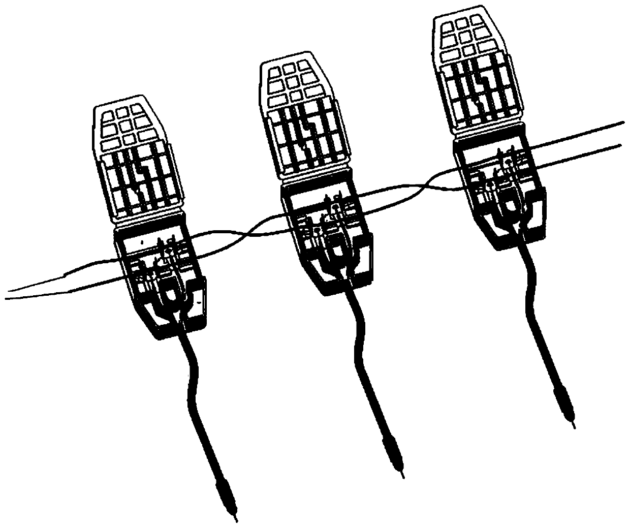
[0038] Embodiment 1: as figure 2 , 3 As shown in , 4, the connecting device at the end of the electronic detonator foot wire includes two sections of detachable male-female butt joints that are mutually detachable. Connecting parts, the male plug-in 1 and the female plug-in 2 can conduct a circuit after being plugged and connected, the male plug-in 1 is connected to the detonating bus 5, and the female plug-in 2 is connected to another section of the detonating bus 5 and the detonator foot wire 4, Both the male plug 1 and the female plug are integrally formed adapters, and the interior is sealed and waterproof after docking. One end of the detonating busbar 5 is connected to the detonator, and the rest of the detonating busbar 5 is divided into several sections and connected between the female plug-in 2 and the male plug-in 1 in turn to form a complete detonating busbar 5. One parallel connection is connected to each electronic detonator, and the electronic detonator is con...

Embodiment 2

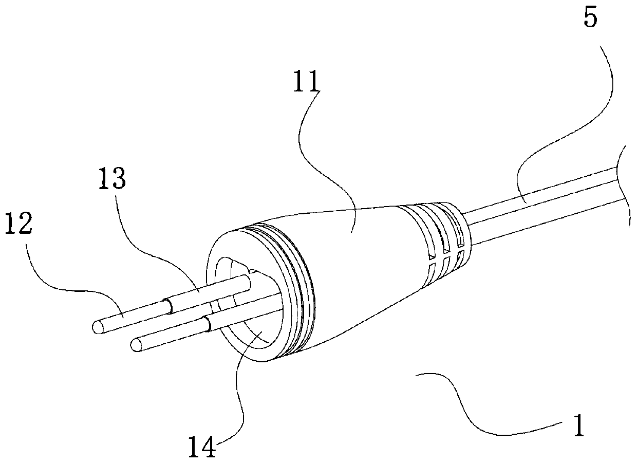
[0039] Embodiment 2: On the basis of Embodiment 1, preferably, the male connector 1 includes a body 11, two pins 12 located at the end of the body 11, and each pin is conductively transmitted to the two electrode wires of the detonating bus 5; The roots of the pins 12 are all wrapped with a layer of waterproof coating or waterproof cover 13; the female plug-in 2 includes a female plug body 21, and two sections are opened in the female plug body 21 to fit the slots 23 of the pins 12. , the slot 23 is provided with a contact ring 24 for contacting with the pin 12, the contact ring 24 is connected to the line electrode 22 built in the female plug body 21, and the line electrode 22 is connected to a group of detonating bus bars 5; The outer end face portion of the slot 23 is partially coated with a waterproof coating or a waterproof ring 25 . In actual use, hold the main body 11, align the pins 12 with the slots 23 on the female plug body 21 of the female plug 2, insert the pins 1...

Embodiment 3

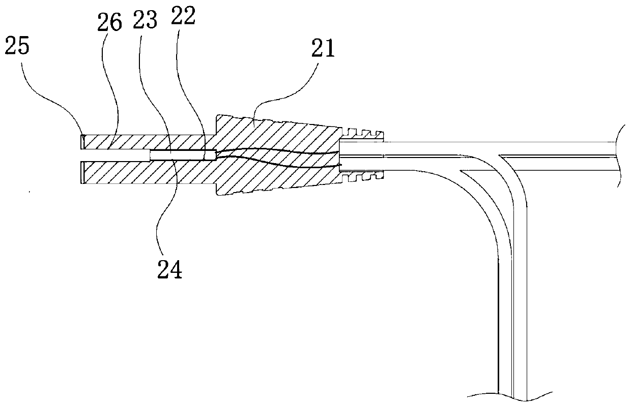
[0041] Embodiment 3: On the basis of Embodiments 1 and 2, the easy-to-fall male and female butt connectors are formed of PVC material as a whole. The body 11 of the male connector 1 has no pins 12, and there is only one dual-circuit plug 3, which is compatible with the earphone plug. The hole structure is similar. The dual circuit plug 3 includes a second contact segment 32 at the root and a first plug segment 31 at the end. The junction between the second contact segment 32 and the first plug segment 31 is insulated Layers are separated; and the female plug body 21 of the female plug-in 2 has only one section of jack 33 that is compatible with the dual-circuit plug 3, and the jack 33 includes two sections of contact sections, which are sequentially from outside to inside The second contact section 35 and the first contact section 34 are separated by an insulating layer and connected to the detonating bus bar 5 and the detonator leg 4 respectively. After connection, the first ...


PUM


Abstract

The invention discloses an electronic detonator leg wire tail end connecting device and an electronic detonator. The electronic detonator leg wire tail end connecting device comprises two sections ofmale and female butt-joint plugs which are mutually detachable and easy to fall off and are not provided with locking connecting components; the male plug is connected with a detonation bus, and the female plug is connected with another section of the detonation bus and a detonator leg wire; the male plug comprises two contact pins, and the contact pins are conductively transmitted to the detonation bus; a waterproof coating or a waterproof sleeve is arranged at the root of each contact pin; and the contact rings are connected with line electrodes arranged in the female plug body, and the lineelectrodes are connected with a set of detonation buses. The outer end surface of a slot is partially coated with a waterproof coating or a waterproof ring; the explosion refusing phenomenon caused by the two problems that the sequential detonation of the adjacent electronic detonators is influenced and needs to be disconnected in time but the metal wire connection cannot be disconnected and theconnection circuit of a non-waterproof junction box is short-circuited when encounters water due to the delay difference of an existing electronic detonator leg wire connection device is fundamentallyovercome; and the set blasting shape and the directional blasting purpose can be achieved.

Description

technical field [0001] The invention relates to the technical field of detonator blasting, in particular to an electronic detonator foot wire terminal connection device and an electronic detonator. Background technique [0002] Electronic detonators, also known as digital electronic detonators, digital detonators or industrial digital electronic detonators, are electric detonators that use electronic control modules to control the detonation process. like figure 1 As shown, in the current electronic detonator blasting system, the tail wires of each electronic detonator are connected in parallel to the detonating bus, and the connection and installation are completed through junction boxes. Usually, several junction boxes are clamped on the detonating bus, and The detonating busbars are all metal wires such as copper core wires. During installation, the skin needs to be peeled off manually to ensure that the cutter touches the copper core wires, and then the detonator and th...

Claims


Application Information

Patent Timeline
Patent Type & Authority Applications(China)
IPC IPC(8): F42C19/12
CPCF42C19/12
Inventor 谢正怀
Owner 谢正怀
Why Eureka
Try Eureka