Watering can control circuit, watering can control device and robot

A technology for controlling circuits and robots, which can be applied to spray devices, water supply devices, disinfection, etc., and can solve the problems of inability to adjust and limit the application scope of epidemic prevention robots.

Active Publication Date: 2021-12-17
UBTECH ROBOTICS CORP LTD
View PDF0 Cites 0 Cited by
  • Summary
  • Abstract
  • Description
  • Claims
  • Application Information

AI Technical Summary

Problems solved by technology

[0004] The purpose of this application is to provide a watering can control circuit, a watering can control device and a robot, aiming to solve the problem that the epidemic prevention robot needs to manually set its spraying rate, which cannot be adjusted at any time according to the scene change, which greatly limits the application range of the epidemic prevention robot.

Method used


Image

  • Watering can control circuit, watering can control device and robot
  • Watering can control circuit, watering can control device and robot
  • Watering can control circuit, watering can control device and robot

Examples


Embodiment Construction

[0031] In order to make the purpose, technical solution and advantages of the present application clearer, the present application will be further described in detail below in conjunction with the accompanying drawings and embodiments. It should be understood that the specific embodiments described here are only used to explain the present application, and are not intended to limit the present application.

[0032] In the description of the present application, it should be understood that the terms "first" and "second" are used for description purposes only, and cannot be interpreted as indicating or implying relative importance or implicitly indicating the quantity of indicated technical features. Thus, a feature defined as "first" and "second" may explicitly or implicitly include one or more of these features.

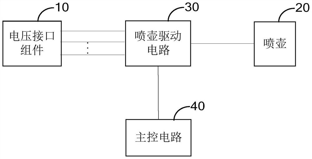
[0033] The embodiment of the present application provides a watering can control circuit, see figure 1 As shown, the watering can control circuit in this embodimen...


PUM


Abstract

This application belongs to the technical field of watering can control, and provides a watering can control circuit, a watering can control device and a robot, wherein the watering can control circuit includes a voltage interface component for providing multiple power supply voltage signals, and the main control circuit is based on the received road identification signal Generate the watering can control signal, the watering can drive circuit receives the watering can control signal and the power supply voltage signal to generate the watering can drive signal to drive the watering can to work, so that the working voltage of the watering can changes with the road, and the anti-epidemic robot needs to manually set its spraying rate, which cannot be set according to Scene changes can be adjusted at any time, which greatly limits the application range of epidemic prevention robots.

Description

technical field [0001] The application belongs to the field of display technology, and in particular relates to a watering can control circuit, a watering can control device and a robot. Background technique [0002] With the development of society and the progress of the times, artificial intelligence technology has entered thousands of households, and the derived intelligent and high-end robots are becoming more and more diverse. Today, with the rapid development of robot technology, robots are becoming more and more intelligent, and their application scenarios are becoming more and more complex. For example, when disinfecting and killing some special places, in order to avoid human infection with viruses, it is necessary to spray disinfection spray liquid to disinfect and kill the environment through epidemic prevention robots. [0003] However, the current anti-epidemic robot needs to manually set its spraying rate, which cannot be adjusted at any time according to the ...

Claims


Application Information

Patent Timeline
Patent Type & Authority Patents(China)
IPC IPC(8): B05B12/12A61L2/24A61L2/18
CPCB05B12/12B05B12/122A61L2/18A61L2/24A61L2202/14A61L2202/16A61L2202/25
Inventor 王玉奇李向龙熊友军
Owner UBTECH ROBOTICS CORP LTD
Why Eureka
Try Eureka