Electric vehicle and power supply control method

An electric vehicle and front-end technology, applied in electric vehicle charging technology, electric vehicle, battery/battery traction, etc., can solve the problems of heavy weight, need to recharge, short driving distance, etc. The effect of charging costs

Inactive Publication Date: 2020-08-07
郭林
View PDF5 Cites 1 Cited by
  • Summary
  • Abstract
  • Description
  • Claims
  • Application Information

AI Technical Summary

Problems solved by technology

Therefore, electric vehicles have developed rapidly in recent years, and the technological changes have been very large. However, the research field of technology is mostly to convert electric energy into kinetic energy as much as possible. Many achievements have been made, but there are still many problems, such as: (1) through charging piles Charging the battery of an electric vehicle takes a long time, has low battery life and short driving distance, and needs to be recharged after the power supply of the battery is used up; (2) the battery of an electric vehicle is charged by a charging pile, which requires a fixed location and equipment. After a full charge, the mileage that can be driven entirely by battery energy storage is limited. When driving on roads or parking lots without charging piles, the car will not be able to drive after the battery power is used up. Therefore, electric vehicles often have no power at all. The charging pile has not been reached while driving; (3) The batteries currently used are large in size and heavy in weight and are not easy to replace. It takes a long time to charge the battery with the charging pile, and the battery charging process takes up a lot of time and space. Increased charging costs

Method used


Image

  • Electric vehicle and power supply control method
  • Electric vehicle and power supply control method
  • Electric vehicle and power supply control method

Examples


Embodiment 1

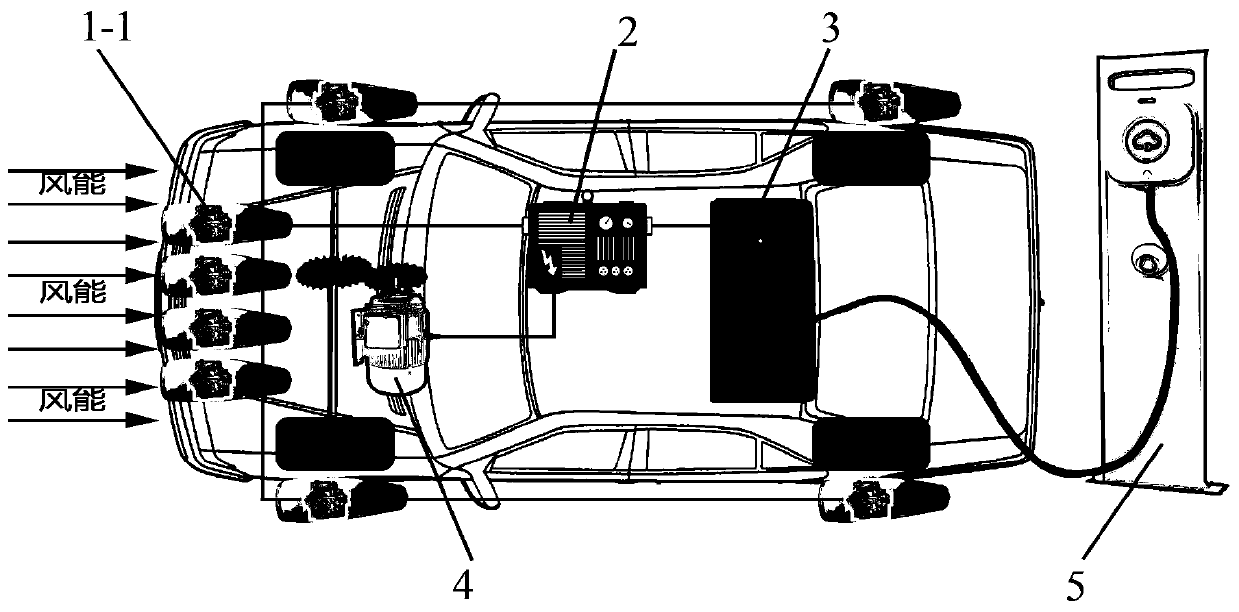
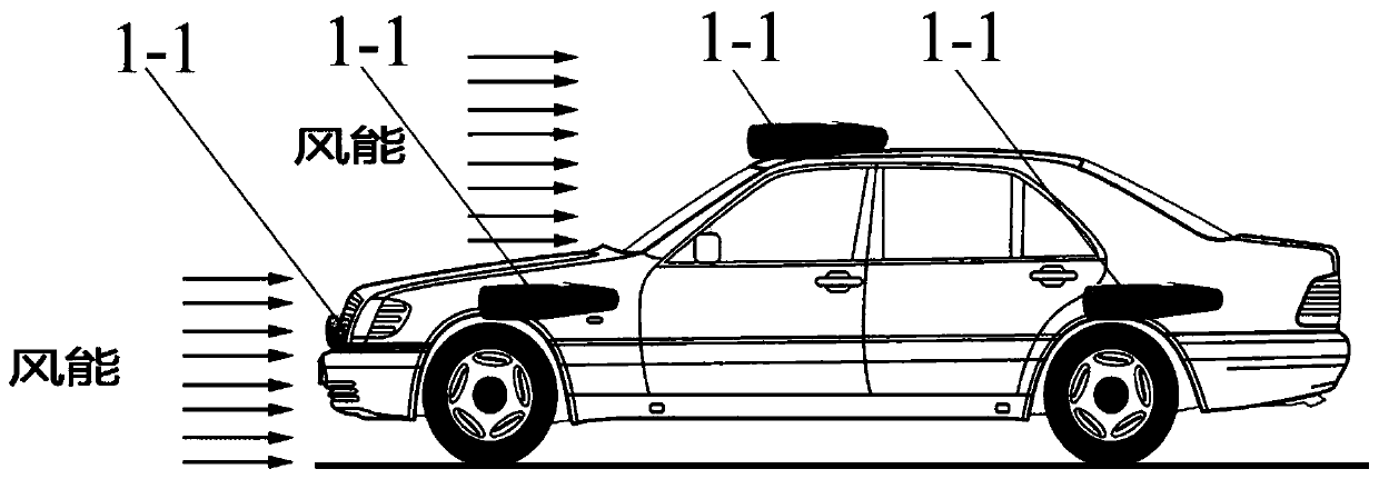
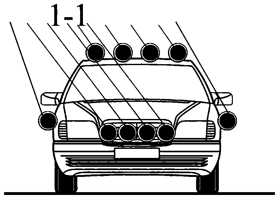
[0039] The auxiliary power generation equipment in this embodiment is a wind power generator. figure 1 It is a structural schematic diagram of Embodiment 1 of the electric vehicle of the present invention, figure 2 It is a side view of Embodiment 1 of the electric vehicle of the present invention, image 3 It is the front view of Embodiment 1 of the electric vehicle of the present invention. combine Figure 1-Figure 3 As shown, in the present embodiment, a plurality of wind generators 1-1 are installed on the front end of the electric vehicle, the top of the vehicle body, and the side of the vehicle body, and the wind kinetic energy generated in the running of the electric vehicle converts wind energy into The electric energy is transmitted to the motor 4 through the inverter 2, and the electric motor 4 converts the electric energy into kinetic energy to drive the electric vehicle; at the same time, the excess electricity generated by the wind generator 1-1 can also be conv...

Embodiment 2

[0041] The difference from Embodiment 1 is that the auxiliary power generation equipment in this embodiment is a fuel generator. Figure 4 It is a structural schematic diagram of electric vehicle embodiment 2 of the present invention, as Figure 4 As shown, in the present embodiment, a fuel generator 1-2 is installed in the hood of the electric vehicle. During the running of the electric vehicle, the fuel generator 1-2 converts energy into electrical energy, and then through the inverter 2 The electric energy is delivered to the motor 4, and the electric motor 4 converts the electric energy into kinetic energy to drive the electric vehicle; the excess electricity generated by the fuel generator 1-2 can also be stored in the storage battery 3, which is used for the electric vehicle and other accessories . The engine of the fuel generator 1-2 in this embodiment is a coolant-cooled engine or an air-cooled engine. Fuel generators 1-2 include: gasoline generators, diesel generato...

Embodiment 3

[0044] The difference from Embodiment 1 is that the auxiliary power generation equipment in this embodiment is a combination of one fuel generator and multiple wind power generators. Figure 7 It is a structural schematic diagram of the electric vehicle embodiment 3 of the present invention, as Figure 7 As shown, the present embodiment at first installs a fuel generator 1-2 in the hood of the electric vehicle, and the fuel generator 1-2 is the same as the fuel generator 1-2 in embodiment 2. During the process, the fuel generator 1-2 converts energy into electric energy, and then transmits the electric energy to the motor 4 through the inverter 2, and the electric motor 4 converts the electric energy into kinetic energy to drive the electric vehicle; secondly, it is installed at the front end of the electric vehicle A plurality of wind power generators 1-1, the wind power generators 1-1 are the same as the wind power generators 1-1 in Embodiment 1, convert wind energy into ele...


PUM


Abstract

The invention relates to an electric vehicle and a power supply control method. The electric vehicle comprises auxiliary power generation equipment, an inverter and a storage battery. The auxiliary power generation equipment is used for generating electric energy; the electric energy output end of the auxiliary power generation equipment is connected to the inverter, and the first output end of the inverter is connected to the first power supply end of a motor of the electric automobile; the second output end of the inverter is connected to the charging end of the storage battery; and the electric energy output end of the storage battery is connected with the second power supply end of a motor. The cruising ability of the electric vehicle can be improved, and the charging cost of the electric vehicle is reduced.

Description

technical field [0001] The invention relates to the field of electric vehicles, in particular to an electric vehicle and a power supply control method. Background technique [0002] As human beings rely on automobiles as a means of transportation, energy consumption continues to increase, and the resulting energy crisis has caused changes in the earth's environment and climate. , bad weather, and global warming. Therefore, electric vehicles have developed rapidly in recent years, and the technological changes have been very large. However, the research field of technology is mostly to convert electric energy into kinetic energy as much as possible. Many achievements have been made, but there are still many problems, such as: (1) through charging piles Charging the battery of an electric vehicle takes a long time, has low battery life and short driving distance, and needs to be recharged after the power supply of the battery is used up; (2) the battery of an electric vehicle...

Claims


Application Information

Patent Timeline
IPC IPC(8): B60L8/00B60L50/60B60L53/00
CPCB60L8/003B60L8/006B60L50/60B60L53/00Y02T10/70Y02T10/7072Y02T10/72Y02T90/14
Inventor 郭林
Owner 郭林
Why Eureka
Try Eureka