
Discharging claw

A material claw and shaft technology, applied in the field of unloading claws, can solve the problems of production line shutdown, increase of galvanized wire processing cost, high labor intensity, etc., and achieve the effect of continuous wire collection

Inactive Publication Date: 2020-08-07
安徽中巨智能科技有限公司
View PDF0 Cites 0 Cited by
  • Summary
  • Abstract
  • Description
  • Claims
  • Application Information

AI Technical Summary

Problems solved by technology

[0002] After the galvanized wire is processed, it is necessary to unload the galvanized wire coil from the production line and cut off the gap between the coil and the galvanized wire on the production line, and then bundle and pack the coil. Unloading is generally manual operation, which is labor-intensive; while the automatic unloading device needs to stop the production line temporarily during unloading, which affects production efficiency, or set up a spare winding roller for transition to achieve continuous operation of the production line. This method indirectly Increased processing cost of galvanized wire

Method used


Image

  • Discharging claw
  • Discharging claw
  • Discharging claw

Examples


Embodiment 1

[0032] Such as figure 1 , 2 Shown, a kind of galvanized wire production system comprises the discharging device 10 arranged in sequence, the upstream guiding device 20, the electroplating tank 30, the downstream guiding device 50, and the unloading device; The discharging device 10 is used for raw material wire Released to the downstream of the production line, the upstream guiding device 20 is used to guide the raw material wire output from the feeding device 10 into the electroplating tank 30, and the electroplating tank 30 is used to electroplate the raw material wire, and the downstream guiding device 50 uses The galvanized wire output from the electroplating tank 30 is transported to the unloading device, and the unloading device is used for winding and collecting the galvanized wire.

[0033] preferred, such as figure 1 , 2 As shown, the discharge device 10 includes a discharge roller, and a discharge drive motor for driving the discharge roller to rotate; the dischar...

Embodiment 2

[0057] A method for processing galvanized wire using the system shown in embodiment 1, comprising the steps:

[0058] Step 1: Place the raw material wire on the galvanizing production line, and manually pull the raw material wire to the end of the production line;

[0059] Step 2: inject electrolyte solution into the electroplating tank 30 of the production line, and start the production line;

[0060] Step 3: After the production line has been running for a period of time, cut and recycle the raw material wire and the initial galvanized wire at the discharge end of the production line; then wind the galvanized wire on the unloading device to collect the galvanized wire;

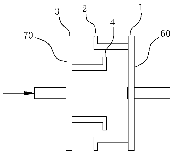
[0061] Step 4: After the galvanized wire on the wire winding roller 60 is wound to a preset length or number of turns, use the unloading claw 70 to unload the galvanized wire coil from the wire winding roller 60, and unload the unloading claw 70 Cut the galvanized wire between the winding roller 60, and the...


PUM


Abstract

The invention belongs to the technical field of metal wire machining, and particularly relates to a discharging claw. The discharging claw comprises a second end plate, the second end plate is fixedlyconnected with a rotating shaft, the rotating shaft is rotationally connected with a piston of a piston cylinder, a plurality of second supporting plates are evenly arranged on the second end plate in the circumferential direction of the rotating shaft at intervals, the second supporting plates are movably connected with the second end plate in the radial direction of the rotating shaft, and thelength directions of the second supporting plates are parallel to the axis direction of the rotating shaft; and the discharging claw further comprises a second driving component for driving the secondsupporting plates to move in the radial direction of the rotating shaft. The discharging claw is arranged to be of an expansion and contraction type structure, the discharging claw can be inserted into a wire winding roller in the winding process of the wire winding roller, galvanized wire rolls on the wire winding roller can be unloaded after being tensioned, and continuous wire winding in the discharging process is achieved.

Description

technical field [0001] The invention belongs to the technical field of metal wire processing, and in particular relates to a discharge claw. Background technique [0002] After the galvanized wire is processed, it is necessary to unload the galvanized wire coil from the production line and cut off the gap between the coil and the galvanized wire on the production line, and then bundle and pack the coil. Unloading is generally manual operation, which is labor-intensive; while the automatic unloading device needs to stop the production line temporarily during unloading, which affects production efficiency, or set up a spare winding roller for transition to achieve continuous operation of the production line. This method indirectly Increased processing cost of galvanized wire. Contents of the invention [0003] The purpose of the present invention is to provide a discharge claw, which can unload the galvanized wire coil on the wire winding roller during the winding process o...

Claims


Application Information

Patent Timeline
Patent Type & Authority Applications(China)
IPC IPC(8): B65B63/04B65B13/18B65B27/06B65H57/14B65H57/16B65H54/70B65H54/20B65H54/44B65H54/28B65H67/04B65H67/052B65H63/08B65H67/02
CPCB65B13/18B65B27/06B65B63/04B65H54/20B65H54/28B65H54/44B65H54/702B65H57/14B65H57/16B65H63/08B65H67/02B65H67/0411B65H67/052B65H2701/36
Inventor 蔡妍其他发明人请求不公开姓名
Owner 安徽中巨智能科技有限公司
Learn More