
Turning tool and turning system with same

A technology for turning over workers and tooling, applied in the field of turning systems, can solve the problems of long construction time, high requirements, and shortage of floating crane resources.

Pending Publication Date: 2020-08-07
HUADIAN HEAVY IND CO LTD
View PDF0 Cites 0 Cited by
  • Summary
  • Abstract
  • Description
  • Claims
  • Application Information

AI Technical Summary

Problems solved by technology

[0005] When a floating crane is used to turn over the pipe pile, the main hook of the floating crane is articulated with the two main lifting lugs of the pipe pile, and the auxiliary hook of the floating crane is articulated with one turning lug of the pipe pile. , the turning of the pipe pile is realized by raising the main hook and lowering the auxiliary hook. In this way, the main hook and auxiliary hook of the floating crane need to meet a certain distance to make the pipe pile turn over smoothly. With the increase of the length and weight of the pipe pile, the force on the main hook and the auxiliary hook of the floating crane increases, and the distance between the main hook and the auxiliary hook also increases. The current floating crane cannot meet this requirement.
[0006] When two floating cranes are used to turn the pipe piles, the requirements for the cooperation between the two are high, the construction cost is high, and the resources of the floating cranes are in short supply, which may affect the construction of the pipe piles, and the construction takes a long time

Method used


Image

  • Turning tool and turning system with same
  • Turning tool and turning system with same
  • Turning tool and turning system with same

Examples


Embodiment Construction

[0032] In order to enable those skilled in the art to better understand the solution of the present invention, the present invention will be further described in detail below in conjunction with the accompanying drawings and specific embodiments.

[0033] For ease of understanding and brevity of description, the turning tool and the turning system with the turning tool will be described below, and the beneficial effects will not be discussed again.

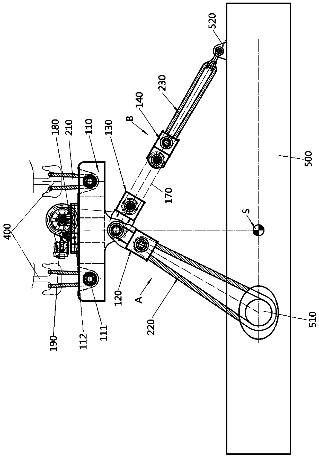
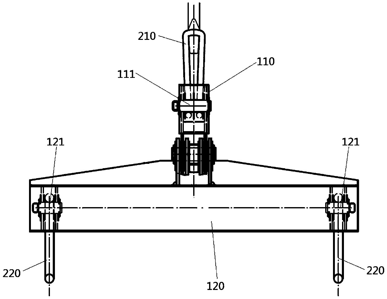
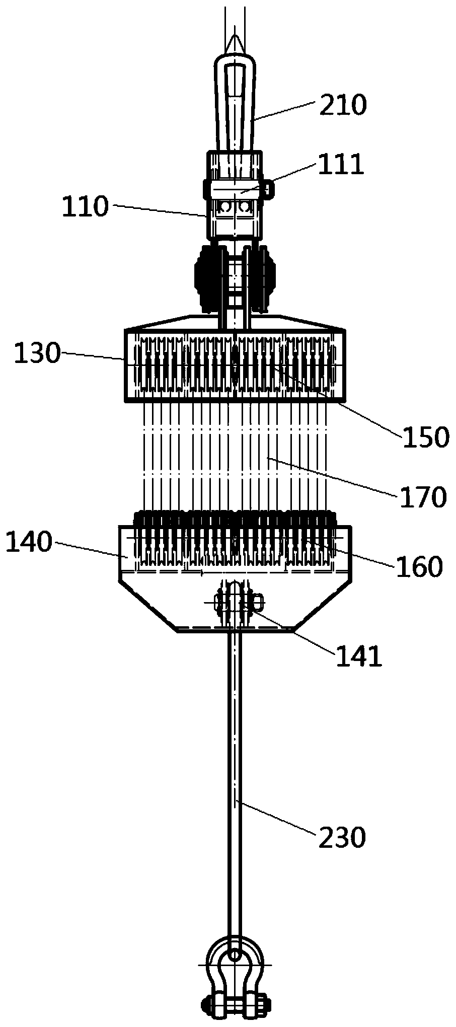
[0034] Please refer to Figure 1 to Figure 5 , figure 1 It is a schematic diagram of the structure after the stand-up tooling is articulated with the hook portion of the pipe pile and the hoisting equipment in the specific embodiment; figure 2 for figure 1 Schematic diagram of the structure from the perspective of A in the middle; image 3 for figure 1 Schematic diagram of the structure of the B-direction perspective; Figure 4 It is a structural schematic diagram of turning over the pipe pile to a certain angle by using the...


PUM


Abstract

The invention discloses a turning tool and a turning system with the same. The turning tool is used for turning over a pipe pile and comprises a lifting beam, a first hanging beam, a second hanging beam and a third hanging beam; the second hanging beam is hinged with the lifting beam; the first hanging beam is hinged with the second hanging beam; and a telescopic structure is arranged between thesecond hanging beam and the third hanging beam. The turning tool further comprises a driving component; the driving component is used for driving the telescopic structure to move to drive the third hanging beam to rise or fall; the lifting beam is provided with at least one lifting point; the first hanging beam is provided with at least two first hanging points; and the third hanging beam is provided with at least one second hanging point. According to the structural design of the turning tool, the turning operation of the pipe pile from a horizontal posture to a vertical posture can be realized only by matching the turning tool with a hook part of hoisting equipment and the operation cost and operation time of pipe pile construction can be reduced.

Description

technical field [0001] The invention relates to the technical field of offshore wind power construction, in particular to a turning tool and a turning system provided with the turning tool. Background technique [0002] Pipe piles are one of the foundation forms of offshore wind farms. During construction, they need to be turned from a horizontal posture to an upright posture before subsequent installation operations can be performed. [0003] With the large-scale development of offshore wind farms, the diameter and weight of pipe piles are getting larger and larger, and the weight of existing pipe piles can reach 1000-2000 tons. [0004] In order to realize the turning of the pipe pile from the horizontal posture to the upright posture, the pile body of the pipe pile is usually provided with three lifting lugs, two main lifting lugs at one end of the pipe pile and one turning lug at the other end of the pipe pile; The pipe pile can be turned over through the cooperation of...

Claims


Application Information

Patent Timeline
IPC IPC(8): B66C1/12B66C13/08
CPCB66C1/12B66C13/08
Inventor 张清涛赵迎九逯鹏宋云峰裴立勤王小合陈冲宪凯袁新勇陈春平魏明华
Owner HUADIAN HEAVY IND CO LTD
Learn More