
Pouring frame fixing formwork structure for civil construction engineering construction

A technology for fixing formwork and engineering construction, which is applied to building construction, on-site preparation of building components, construction, etc. It can solve problems such as inconvenient pouring work, poor sealing performance, and poor sealing effect, and achieve fast installation and fixing, and work The effect of improving efficiency and ensuring connection strength

Active Publication Date: 2020-08-07
LIAONING PROVINCIAL TRANSPORTATION PLANNING & DESIGN INST
View PDF6 Cites 3 Cited by
  • Summary
  • Abstract
  • Description
  • Claims
  • Application Information

AI Technical Summary

Problems solved by technology

[0003] The existing pouring frame fixing formwork structure is usually fixed with screws, iron nails, etc. Since the fasteners need to be fixed one by one, the fixing operation steps are cumbersome, and it is not easy to assemble. After the pouring frame is fixed, it is easy to leave a large The gaps in the gaps, the sealing effect is poor, and it is not convenient for pouring work. At the same time, screws, iron nails and other objects are used to fix the pouring frame. The board is separated and falls off, or the top of the baffle is forced to tilt outward, thus affecting the construction of the building
[0004] The existing fixed formwork for pouring frames uses more than one layer of fixing plates to fix the pouring beams during use, and the sealing performance during use is poor and the disassembly process is too cumbersome

Method used


Image

  • Pouring frame fixing formwork structure for civil construction engineering construction
  • Pouring frame fixing formwork structure for civil construction engineering construction
  • Pouring frame fixing formwork structure for civil construction engineering construction

Examples


Embodiment Construction

[0027] In order to make the above objects, features and advantages of the present invention more comprehensible, specific implementations of the present invention will be described in detail below in conjunction with the accompanying drawings. In the following description, numerous specific details are set forth in order to provide a thorough understanding of the present invention. However, the present invention can be implemented in many other ways different from those described here, and those skilled in the art can make similar improvements without departing from the connotation of the present invention, so the present invention is not limited by the specific implementations disclosed below.

[0028] It should be noted that when an element is referred to as being “fixed” to another element, it can be directly on the other element or there can also be an intervening element. When an element is referred to as being "connected to" another element, it can be directly connected ...


PUM


Abstract

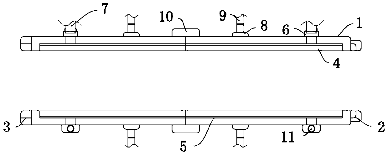
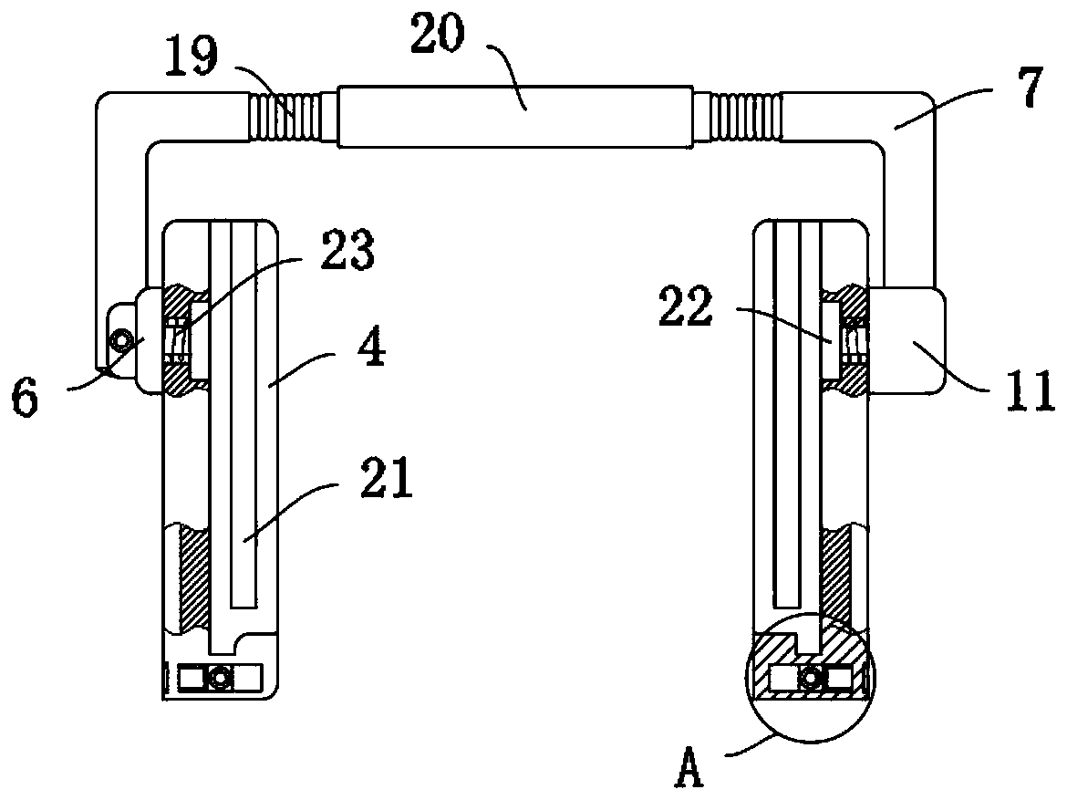
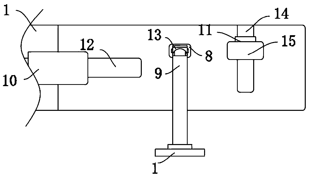
The invention discloses a pouring frame fixing formwork structure for civil construction engineering construction. The pouring frame fixing formwork structure for the civil construction engineering construction comprises two symmetrically arranged fixing formworks, installing grooves are formed in the fixing formworks, vertical moving grooves are formed in the side walls of the fixing formworks, adjusting rod mechanisms for realizing clamping and fixing of the fixing formworks are arranged in the vertical moving grooves, fixing bases are fixedly connected to the side walls of the fixing formworks, movable supporting rod mechanisms used for supporting the fixing formworks are arranged on the fixing bases, and horizontal moving grooves are formed in the side walls of the fixing formworks. The pouring frame fixing formwork structure is reasonable in structure, the fixing degree of the fixing formworks is conveniently adjusted by arranging the adjusting rod mechanisms, meanwhile, the fixing formworks is conveniently detached after pouring solidification, the working efficiency is improved, the fixing formworks is conveniently supported by arranging the movable supporting rod mechanisms, the supporting effect is guaranteed, and meanwhile rapid fixing between the movable supporting rod mechanisms and the fixing formworks is achieved.

Description

technical field [0001] The invention relates to the technical field of punch engineering construction, in particular to a pouring frame fixing formwork structure for civil engineering construction. Background technique [0002] Civil engineering, that is, civil construction engineering, is the general term for civil engineering and construction engineering. It is an engineering discipline that builds various facilities and places for human life, production, protection and other activities, covering ground, underground, land, water, water Construction of buildings, structures and engineering objects within the scope of various projects such as housing, roads, railways, airports, bridges, water conservancy, ports, tunnels, water supply and drainage, protection, etc. During the construction process of the project, it is necessary to use the frame fixed formwork structure to standardize the scope of pouring, and perform pouring work on main positions such as beams and foundation...

Claims


Application Information

Patent Timeline
Patent Type & Authority Applications(China)
IPC IPC(8): E04G13/04
CPCE04G13/04
Inventor 徐悌
Owner LIAONING PROVINCIAL TRANSPORTATION PLANNING & DESIGN INST
Learn More