Locking device and method

A locking device and lock tongue technology, which is applied in the direction of building fastening devices, wing leaf fastening devices, buildings, etc., can solve the problems of loss of expected locking performance, poor shielding and sealing of electrical cabinet doors, and high assembly requirements. It achieves the effect of eliminating the unsatisfactory deformation and locking of the device, reducing the difficulty of design and manufacturing, and clear and concise external interface

Pending Publication Date: 2020-08-07
CHINA ELECTRONICS TECH GRP CORP NO 14 RES INST
View PDF0 Cites 0 Cited by
  • Summary
  • Abstract
  • Description
  • Claims
  • Application Information

AI Technical Summary

Problems solved by technology

[0004] There are too many parts in the internal structure of the device, resulting in high assembly requirements and complicated processes. Generally, after assembly, the angle and clearance of the connection points need to be adjusted to achieve the purpose of adjusting the pre-tightening force.
When this device is used on the electrical cabinet door with rubber strip shielding and sealing, this kind of pretightening force adjustment is often not well controlled, which will lead to overpressure of the pretightening force and lead to life reduction or even pressure loss of the rubber strip. If it is too loose, the shielding seal of the electrical cabinet door is not tight
[0005] There are inevitable inherent defects in the design of this device. There are clearances between some of its structural parts. The multi-level low-rigidity connections of long-arm connecting rods, rotating arms and other components will cause stress and deformation. Often after the product is transported and circulated, Or after long-term use, the device may lose the expected locking performance, especially in products with clear vibration and shock requirements such as vehicles and ships, it is not suitable to use this device

Method used


Image

  • Locking device and method
  • Locking device and method
  • Locking device and method

Examples


Embodiment Construction

[0029] The preferred mechanism and motion realization method of the present invention will be further described below in conjunction with the accompanying drawings and specific embodiments.

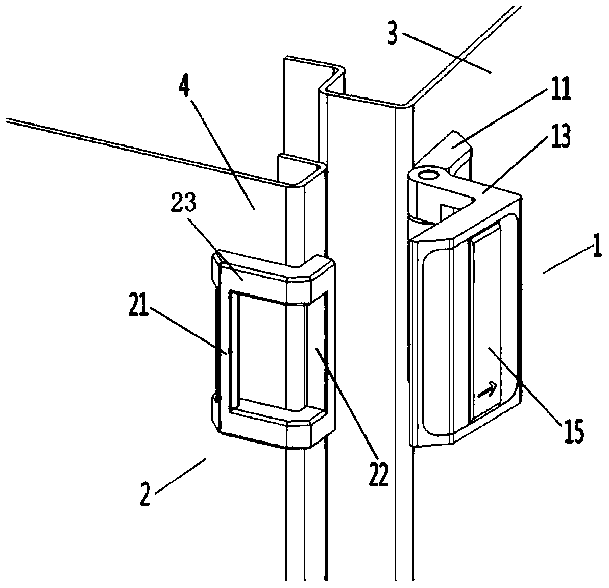
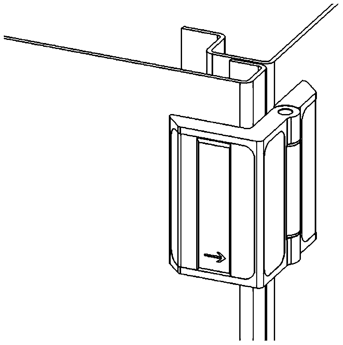
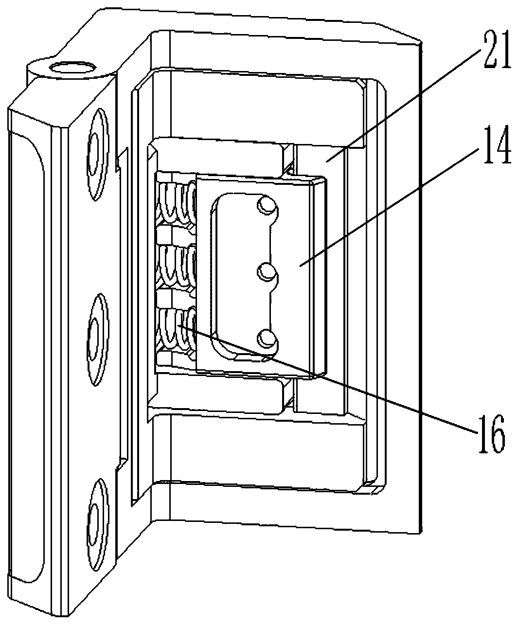
[0030] Such as Figure 1-5 As shown, a locking device includes a lock body 1 and a lock hook 2, the lock body 1 is installed on the door frame 3 of the electrical cabinet, and the lock hook 2 is installed on the cabinet door 4 of the electrical cabinet.

[0031] Wherein, the locking hook 2 is one piece, including a main locking hook 21 and a secondary locking hook 22 , and the two ends of the main locking hook 21 and the secondary locking hook 22 are respectively connected by two L-shaped connecting rods 23 . The L-type connecting rod 23 is arranged horizontally along the outer surface of the cabinet door 4, and the corresponding main lock hook 21 is installed on the front of the cabinet door 4 in a vertical state, and the auxiliary lock hook 22 is installed on the side of the cabinet doo...


PUM


Abstract

The invention discloses a locking device and method. The locking device is used for locking between a first main body and a second main body and comprises a lock body and a lock hook, wherein the lockhook is fixedly installed on the edge of the first main body and comprises a main lock hook body, the lock body is hinged to the edge of the second main body and comprises a rotatable movable block,a spring bolt, an unlocking sliding block and an elastic piece are arranged on the movable block, the unlocking sliding block is fixedly connected with the spring bolt and can drive the spring bolt tostretch out and draw back by shifting the sliding block, and the elastic piece is connected with the spring bolt and used for enabling the spring bolt to have the stretching-out trend. The locking device serves as a complete set of independent mechanism, long arm piece and low-rigidity connecting structure design is avoided, the structure is exquisite and compact, the appearance is attractive, anexternal interface is clear and concise and simple, assembling is convenient and quick; and the pre-tightening force does not need to be adjusted after installation, a safe and reliable pre-tightening force can be obtained after the device is locked, and the phenomenon that the device is not ideal in deformation locking is effectively eradicated.

Description

technical field [0001] The invention belongs to the technical field of electrical equipment, and in particular relates to a locking device and method. Background technique [0002] At present, the locking devices of electrical cabinet doors can be mainly divided into multi-point locking devices and single-point locking devices according to the layout of their locking points. These locking devices are based on the consideration of safety, shielding, sealing, etc. rear lock. Generally speaking, the linkage multi-point locking device has a complex mechanism, and is more suitable for fast locking of large electrical cabinet doors, and such complicated devices are not required for small electrical cabinet doors. In some occasions, through reasonable and effective design, the single-point locking device can effectively replace the multi-point locking device of the connecting rod. The following problems generally exist in the use of this type of connecting rod multi-point locking...

Claims


Application Information

Patent Timeline
Patent Type & Authority Applications(China)
IPC IPC(8): E05C19/00E05C19/08
CPCE05C19/00E05C19/08
Inventor 向树国
Owner CHINA ELECTRONICS TECH GRP CORP NO 14 RES INST
Why Eureka
Try Eureka