Yarn pressing device and working method of flat knitting machine

A technology of flat knitting machine and yarn pressing, which is applied in knitting, weft knitting, textile and paper making, etc., can solve the problem of high probability of looped floating sheets, reduce the probability of looped floating sheets, control production costs, and structural design. optimized effect

Active Publication Date: 2022-05-17
桐乡市强隆机械有限公司
View PDF12 Cites 1 Cited by
  • Summary
  • Abstract
  • Description
  • Claims
  • Application Information

AI Technical Summary

Problems solved by technology

[0002] Computerized flat knitting machines need to be filled with a large amount of yarn when weaving. In order to prevent yarn floating, yarn pressing devices are usually installed on the front and rear needle beds to press the yarn so that it does not float up. The sinker in the existing yarn pressing device is usually Threaded on a positioning steel wire, as shown in the patent application with publication number CN111005143A, under the power drive, the sinker rotates with the positioning steel wire as the rotating shaft, and the sinker with this structure still has the possibility of forming loops and floating pieces High shortcomings, so it is necessary to improve and optimize it

Method used


Image

  • Yarn pressing device and working method of flat knitting machine
  • Yarn pressing device and working method of flat knitting machine
  • Yarn pressing device and working method of flat knitting machine

Examples


Embodiment Construction

[0041] The present invention will be further described in detail below in conjunction with the accompanying drawings and examples. The following examples are explanations of the present invention and the present invention is not limited to the following examples.

[0042] Example.

[0043] see Figure 1 to Figure 8 .

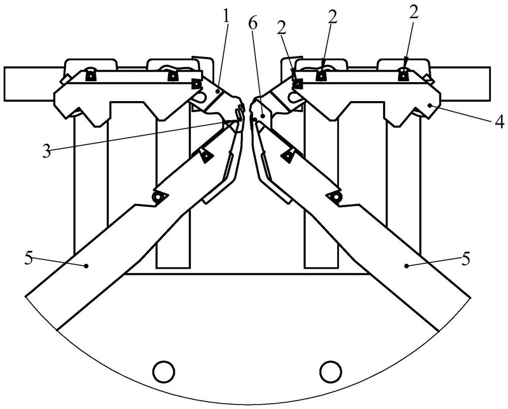
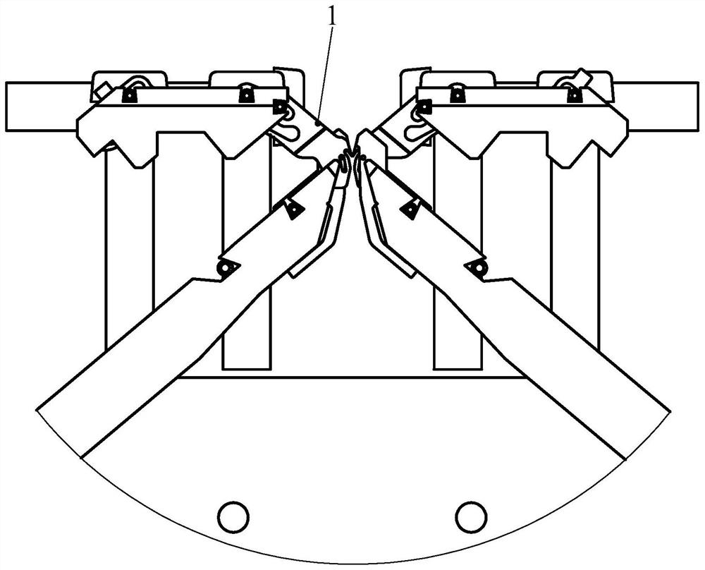
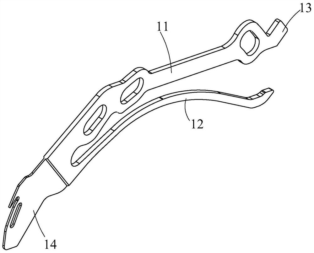
[0044] This embodiment discloses a yarn pressing device of a flat knitting machine, which includes a sinker 1 and a sinker needle plate 4 . Two sinker needle plates 4 are arranged symmetrically above the needle bed 5 of the flat knitting machine. The needle bed 5 is divided into a front needle bed and a rear needle bed. The front and rear needle beds are also symmetrically arranged front and rear. The sinker needle board 4 is arranged above the front needle bed, and the other sinker needle board 4 is arranged above the rear needle bed. Rows of knitting needles are arranged on the front and rear needle beds.

[0045] In this embodiment, the sinker needle plat...


PUM


Abstract

The invention relates to a yarn pressing device of a flat knitting machine and a working method thereof. The sinker is installed in a sinker containing groove; the sinker includes a sinker body, an elastic presser foot part, a power heel part and a yarn pressing part; There are three rotation positioning holes on the body, and a through hole for limit on the yarn pressing part; there are three through slots on the sinker needle plate, and one No. 1 positioning steel wire is installed in each through slot, and three one No. 1 positioning steel wires respectively pass through three rotating positioning holes; the axis lines of the three No. 1 positioning steel wires are not on the same straight line as the three intersection points generated by the same cross section, and the three intersection points determine a virtual circle, and the centers of all virtual circles A virtual axis line is formed; under the action of power, the heel of the power plate makes the sinker rotate back and forth around the virtual axis line. The yarn pressing device reduces the requirements for the use of rollers, presser feet and other flat knitting machine mechanisms during weaving, facilitates the structural design optimization of the integrated garment machine, and is beneficial to control the overall production cost.

Description

technical field [0001] The invention relates to the technical field of computerized flat knitting machines, in particular to a yarn pressing device of a flat knitting machine and a working method thereof. Background technique [0002] Computerized flat knitting machines need to be filled with a large amount of yarn when weaving. In order to prevent yarn floating, yarn pressing devices are usually installed on the front and rear needle beds to press the yarn so that it does not float up. The sinker in the existing yarn pressing device is usually Threaded on a positioning steel wire, as shown in the patent application with publication number CN111005143A, under the power drive, the sinker rotates with the positioning steel wire as the rotating shaft, and the sinker with this structure still has the possibility of forming loops and floating pieces High shortcomings, so it is necessary to improve and optimize it. Contents of the invention [0003] The object of the present in...

Claims


Application Information

Patent Timeline
Patent Type & Authority Patents(China)
IPC IPC(8): D04B15/06D04B15/24
CPCD04B15/06D04B15/24
Inventor 陈崇安勇强王靖敏钟佳明张锋
Owner 桐乡市强隆机械有限公司
Why Eureka
Try Eureka