Mechanical model device for rotor of motor

A technology of mechanical models and rotors, applied in the direction of measuring devices, testing of mechanical parts, testing of machine/structural parts, etc., can solve problems such as troublesome end fixing, waste, consuming a lot of manpower, material resources and time, saving manpower and material resources, simple installation and easy operation

Active Publication Date: 2015-12-23
DONGFANG ELECTRIC MACHINERY
View PDF9 Cites 1 Cited by
  • Summary
  • Abstract
  • Description
  • Claims
  • Application Information

AI Technical Summary

Problems solved by technology

[0004] In the prior art, for a 100-megawatt-level high-speed speed-adjustable hydro-generator, when the unit is running away, the circumferential speed of the rotor is relatively high, generally reaching 180m / s, and the entire wound rotor structure is under a huge centrifugal force. The safety and reliability of the rotor winding and the guarantee of the electrical insulation performance of the rotor winding need to be verified. Therefore, it is necessary to check the performance of different winding end fixing structures, as well as the safety reliability and electrical insulation performance of the rotor winding under the runaway condition of the unit. testing, so as to find out the best performance and the most stable end fixing structure, but in the prior art, the debugging and testing are carried out on the 100-megawatt-level high-speed speed-adjustable hydro-generator. During the testing process, Due to the large size of the rotor of the 100-megawatt high-speed adjustable-speed hydro-generator, it is troublesome and time-consuming to fix the end, and it is inconvenient to replace different end fixing schemes. It consumes a lot of manpower, material resources and time, causing unnecessary waste

Method used


Image

  • Mechanical model device for rotor of motor
  • Mechanical model device for rotor of motor
  • Mechanical model device for rotor of motor

Examples


Embodiment 1

[0052] As a preferred embodiment of the present invention, with reference to the attached figure 1 , this example discloses

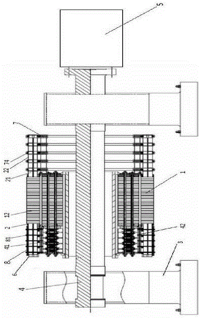
[0053] A rotor mechanical model device of a motor, comprising a support frame 3, a support shaft 4 and a drive mechanism 5, one end of the support shaft 4 is connected to the drive mechanism 5, and rotates under the drive of the drive mechanism 5; the support frame 3 supports Below the supporting shaft 4, the supporting shaft 4 and the supporting frame 3 are relatively rotated; the supporting shaft 4 is provided with a rotor 1 matched with the end fixing device 6, and the rotor 1 rotates with the rotation of the supporting shaft 4 .

Embodiment 2

[0055] As another preferred embodiment of the present invention, with reference to the attached figure 1 , this example includes

[0056] A rotor mechanical model device of a motor, comprising a support frame 3, a support shaft 4 and a drive mechanism 5, one end of the support shaft 4 is connected to the drive mechanism 5, and rotates under the drive of the drive mechanism 5; the support frame 3 supports Below the supporting shaft 4, the supporting shaft 4 and the supporting frame 3 are relatively rotated; the supporting shaft 4 is provided with a rotor 1 matched with the end fixing device 6, and the rotor 1 rotates with the rotation of the supporting shaft 4 . The rotor 1 is formed by laminating a number of silicon steel sheets, and the rotor 1 is provided with a number of radial ventilation grooves 12; the rotor is provided with a rotor winding 2, and the rotor 1 is provided with an axial winding Slots 11 , into which axial winding bars 21 of the rotor winding 2 are insert...

Embodiment 3

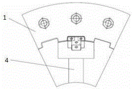
[0058] As another preferred embodiment of the present invention, with reference to the attached figure 1 and 2 , this example discloses

[0059] A rotor mechanical model device of a motor, comprising a support frame 3, a support shaft 4 and a drive mechanism 5, one end of the support shaft 4 is connected to the drive mechanism 5, and rotates under the drive of the drive mechanism 5; the support frame 3 supports Below the supporting shaft 4, the supporting shaft 4 and the supporting frame 3 are relatively rotated; the supporting shaft 4 is provided with a rotor 1 matched with the end fixing device 6, and the rotor 1 rotates with the rotation of the supporting shaft 4 . The rotor 1 is formed by laminating a number of silicon steel sheets, and the rotor 1 is provided with a number of radial ventilation grooves 12; the rotor is provided with a rotor winding 2, and the rotor 1 is provided with an axial winding Slots 11 , into which axial winding bars 21 of the rotor winding 2 ar...


PUM


Abstract

The invention discloses a mechanical model device for a rotor of a motor and relates to the technical field of test machinery. The mechanical model device comprises a rotor and a rotor winding, wherein an axial winding slot is arranged along an axial direction of the rotor; a winding bar of the rotor winding is inserted into the axial winding slot; a winding tail end of the winding bar exposed from the axial direction of the rotor is formed into an end winding; end fixing devices are fixedly arranged at the two ends of the rotor; the end fixing devices are used for fixing the end winding. The mechanical model device is fit for high-capacity winding type rotor machinery, especially for the experimental research for the fixing mode of the rotor winding end and the detection and test analysis for the safe reliability of the fixing of the winding bar end of the rotor and the electric insulating property of the rotor winding.

Description

technical field [0001] The invention relates to the technical field of test machinery, in particular to a rotor mechanical model device of an electric motor. Background technique [0002] The speed-adjustable hydro-generator realizes the flexible connection between the motor speed and the power supply frequency. By changing the frequency of the rotor winding connected to the alternating current, the magnetic field established by the rotor current can be adjusted relative to the rotor speed, and the actual operating speed of the unit can be adjusted within a certain range. . When the rotor of the speed-adjustable hydro-generator adopts a winding structure, the rotor coil is composed of strip-type wire rods. When the speed-adjustable hydro-generator is running at high speed, different from the traditional salient-pole synchronous motor, the centrifugal force generated by the excitation coil is no longer supported by the magnetic pole core shoe, and it is necessary to set up c...

Claims


Application Information

Patent Timeline
Patent Type & Authority Applications(China)
IPC IPC(8): G01M13/00G01R31/12
Inventor 郑小康骆林刘健俊郝金伟龚春源
Owner DONGFANG ELECTRIC MACHINERY
Why Eureka
Try Eureka