Electric connector

A technology for electrical connectors and docking parts, applied in the field of electrical connectors, can solve the problems of blocking installation space, difficulties in making and assembling conductive terminals, and reducing the height of electrical connectors, so as to achieve low overall height and center height and reduce manufacturing difficulty and production cost, to solve the effect of difficult assembly

Pending Publication Date: 2020-08-07
ALLTOP ELECTRONICS SU ZHOU
View PDF0 Cites 0 Cited by
  • Summary
  • Abstract
  • Description
  • Claims
  • Application Information

AI Technical Summary

Problems solved by technology

[0003] In addition, in order to facilitate the electrical connection between the electrical connector and the mating components, it is necessary to reduce the height of the electrical connector, and at this time it becomes more difficult to manufacture and assemble conductive terminals with a large number of pieces.
Taking an electrical connector with four power terminals arranged in the height direction as an example, according to the traditional manufacturing process, if the power terminal pair on the upper side is first installed in the insulating body, and then the solder legs of the power terminal pair on the lower side are folded After being bent and put into the insulating body, when the center height of the electrical connector is set to be low, it will be difficult for the power terminal pair on the upper row to be bent to form a downwardly extending solder leg; if the power terminal on the upper side is first Bending in half to form a downward welding leg and then putting it into the insulating body will block the installation space of the power terminal pair on the lower side, so that the power terminal pair on the lower side cannot be put into the insulating body

Method used


Image

  • Electric connector
  • Electric connector
  • Electric connector

Examples


Embodiment Construction

[0025] The present invention will be described in detail below with reference to the embodiments shown in the accompanying drawings. However, this embodiment does not limit the present invention, and any structural, method, or functional changes made by those skilled in the art according to this embodiment are included in the protection scope of the present invention.

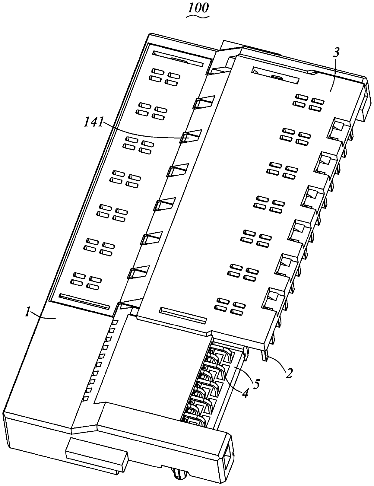
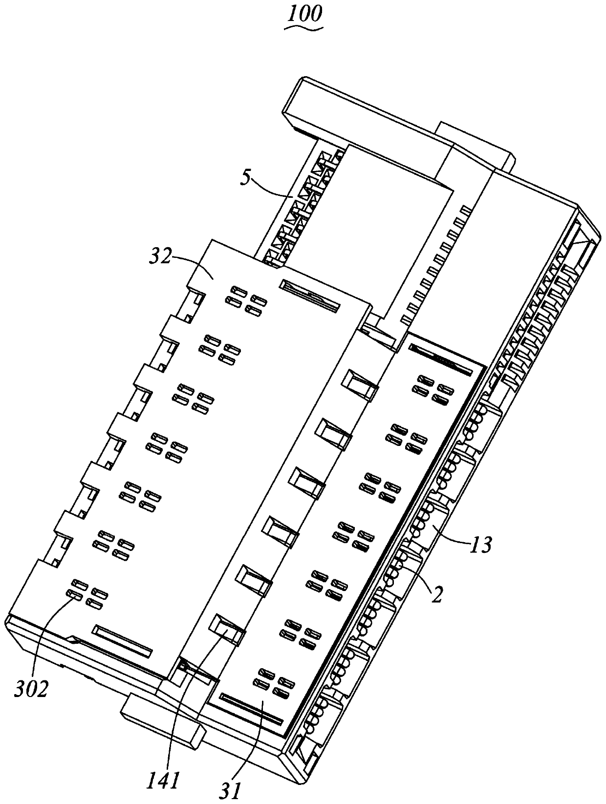
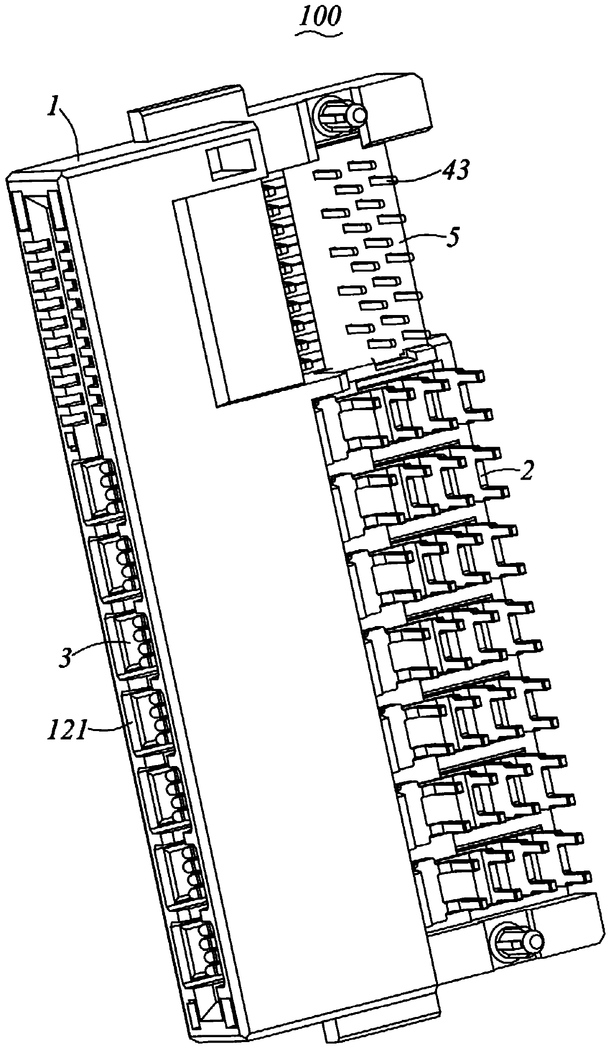
[0026] Please refer to Figure 1 to Figure 10 Shown is a preferred embodiment of the electrical connector 100 of the present invention, the electrical connector 100 includes an insulating body 1 and a plurality of power terminal pairs 2 fixed to the insulating body 1 . For ease of description, the following description will take the butt end of the electrical connector 100 as the front end, and the other end opposite to the butt end as the rear end for description, that is, the front and rear direction is the direction between the electrical connector 100 and the mating component (not shown). The butt joint di...


PUM


Abstract

The invention provides an electric connector. The electric connector is provided with an insulating body and a plurality of power supply terminal pairs fixed on the insulating body. The insulation body is provided with an installation part used for being installed on a circuit board, a butt joint part extending forwards from the installation part and a plurality of terminal grooves extending in the front-back direction. The power supply terminal pairs are fixed in the corresponding terminal grooves of the insulating body and are divided into two rows arranged in the height direction; each power supply terminal pair in each row comprises two power supply terminals; each power supply terminal comprises a holding part held in the corresponding terminal groove, at least one pair of contact parts formed by extending forwards from the front end of the holding part, and at least one welding foot formed by bending and extending from the rear end of the holding part; one row of power supply terminal pairs is inserted into the insulating body in the direction from back to front, and the other row of power supply terminal pairs is inserted into the insulating body in the vertical direction. The electric connector is convenient to manufacture, low in height and convenient to electrically connect.

Description

technical field [0001] The invention relates to an electrical connector, in particular to an electrical connector with a relatively low height. Background technique [0002] In traditional electrical connectors, the transmission area of ​​the power terminals is increased to form a sheet structure in order to transmit large currents. Each power terminal usually has one or more contact arms extending forward from the front end of its sheet body. At the same time, the multi-chip power terminals arranged along the height direction are used to realize the purpose of transmitting a larger current. [0003] In addition, in order to facilitate the electrical connection between the electrical connector and the mating components, the height of the electrical connector needs to be reduced, and at this time it becomes more difficult to manufacture and assemble the conductive terminals with a large number of pieces. Take an electrical connector with four power terminals arranged in the ...

Claims


Application Information

Patent Timeline
Patent Type & Authority Applications(China)
IPC IPC(8): H01R13/631H01R13/40H01R13/02H01R13/502H01R12/71
CPCH01R13/631H01R13/40H01R13/02H01R13/502H01R12/716H01R12/58H01R12/724H01R12/7088H01R12/707H01R13/506H01R13/41H01R13/424
Inventor 张志辉殷定彬
Owner ALLTOP ELECTRONICS SU ZHOU
Why Eureka
Try Eureka