

Doubly-fed induction motor phase-locked-loop-free power control method and device
A doubly-fed induction motor, no phase-locked loop technology, applied in motor generator control, generator control circuit, asynchronous generator control and other directions, can solve the problem of complex and cumbersome decoupling control, to simplify the calculation process, ensure no Effects of differential tracking and decoupling control
- Summary
- Abstract
- Description
- Claims
- Application Information
AI Technical Summary
Problems solved by technology
Method used
Image

Examples
Embodiment 1
[0056] A method for power control of doubly-fed induction motor without phase-locked loop
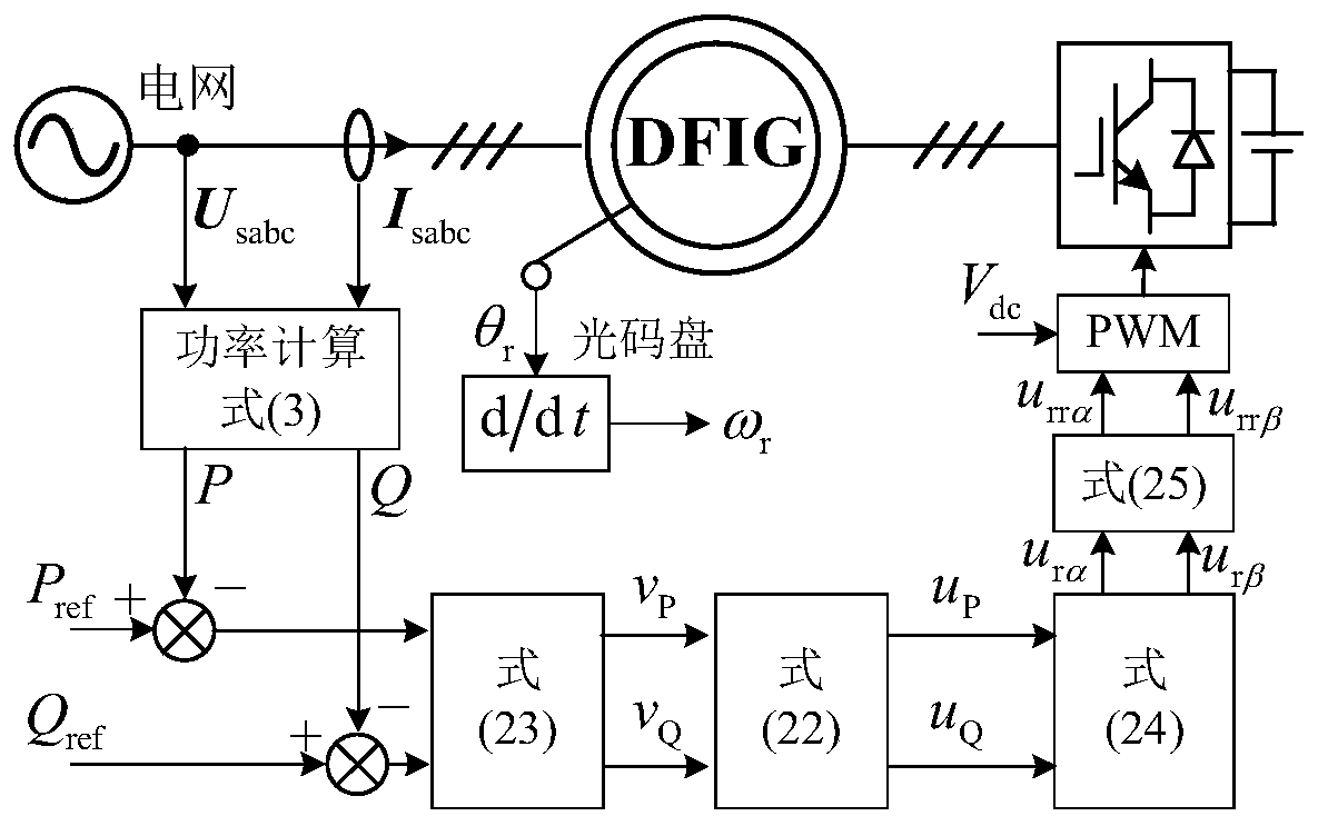
[0057] Such as figure 1 shown, including the following steps:
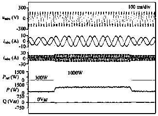
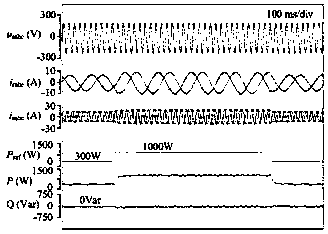
[0058] Step 1: Collect the instantaneous value of the stator voltage and current of the motor, and calculate the active power P and reactive power Q output by the motor stator.
[0059] Through the sensor, the stator three-phase voltage and current instantaneous value of the doubly fed induction generator (DFIG) is collected, and then the collected motor stator voltage signal is band-pass filtered through the power frequency band-pass filter. get
[0060]
[0061]
[0062] In the formula, s is the Laplacian operator, ω 1 =100πrad / s is the rated frequency, ξ is the damping ratio, u sa_mea1 , u sb_mea1 , u sc_mea1 is the instantaneous value of the three-phase stator voltage processed by the band-pass filter; u sa_mea , u sb_mea , u sc_mea Respectively represent the collected instantaneous values of the three-...
Embodiment 2
[0129] Power control device for doubly-fed induction motor without phase-locked loop
[0130] include:
[0131] The sensor is installed on the stator of the motor and is used for collecting instantaneous values of stator voltage and current.
[0132] A power regulator, the signal input terminal of the power regulator is connected to the power output terminal of the motor stator, and is used to adjust the active power P and reactive power Q output by the motor stator; the signal input terminal of the power regulator is connected to the motor stator power output. Can be used including but not limited to proportional (proportion) P regulator, proportional integral (proportion integral) PI regulator, proportional integral differential (proportion integral differential) PID regulator, proportional integral resonant (proportion integral resonant) PIR regulator, sliding mode regulator linear or non-linear regulators such as
[0133] A control signal calculation unit, the control...
PUM
 Abstract
Description
Claims
Application Information