
A paper cutting device
A paper and rack technology, applied in the field of paper slitting devices, can solve the problems of paper roll falling, affecting the rewinding of base paper, etc., and achieve the effects of smooth winding, lower center of gravity, and improved stability
Patent Information
- Authority / Receiving Office
- CN · China
- Patent Type
- Patents(China)
- Current Assignee / Owner
- Publication Date
- 2022-03-22
Smart Images
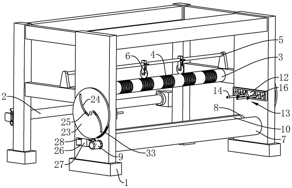
Figure 1 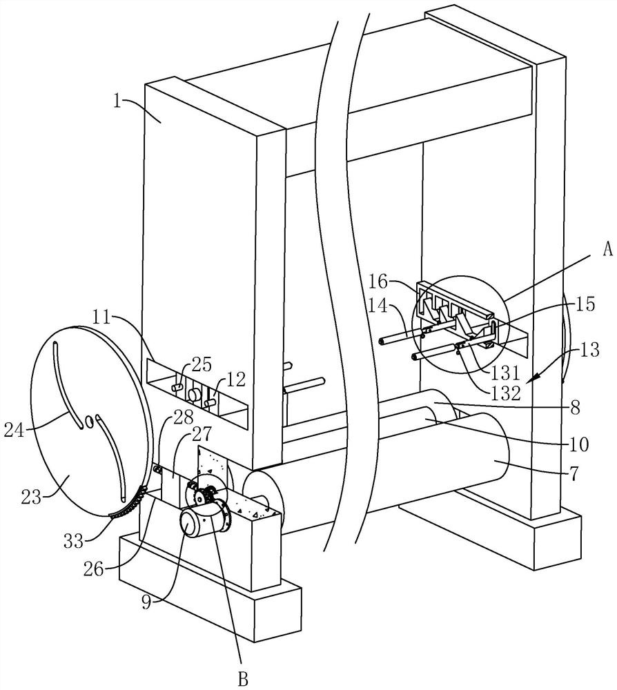
Figure 2 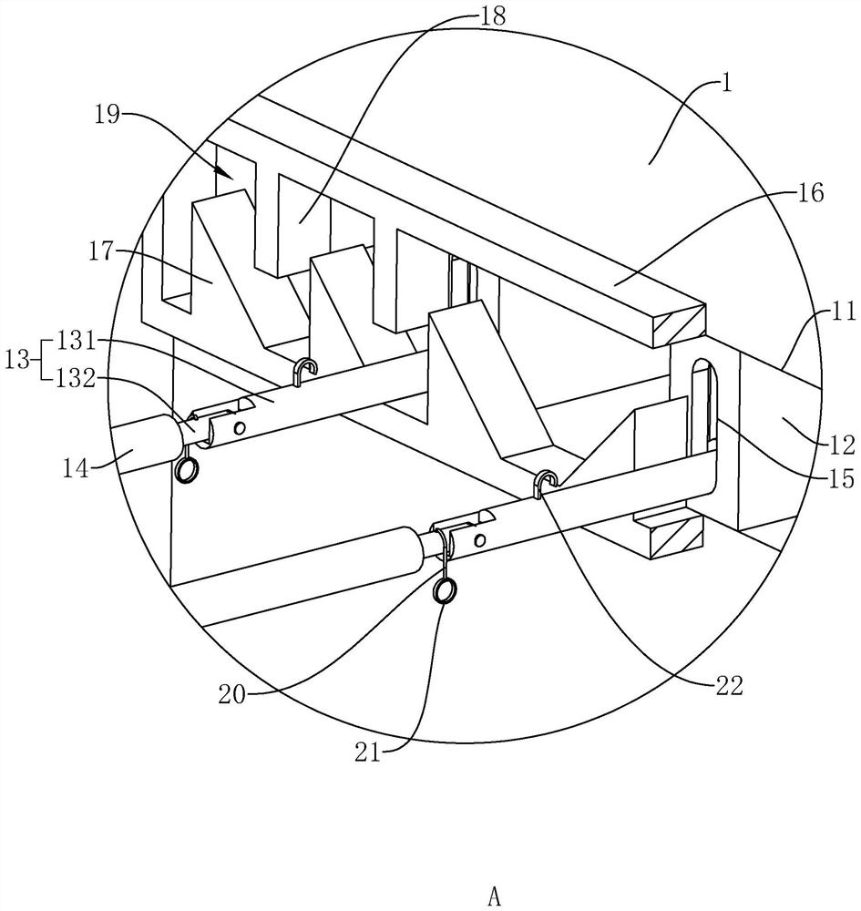
Figure 3
Abstract
Description
technical field
[0001] The invention relates to the technical field of paper production, in particular to a paper cutting device. Background technique
[0002] The technological process of paper production is as follows: pulping→pulping→forming→drying→creping→rolling paper→base paper→rewinding. The rewinding includes three steps of unwinding the base paper, cutting the base paper and rolling up the base paper again. The function of rewinding mainly includes (1) cutting off the burrs of the base paper; (2) because the diameter and width of the base paper are large, the large roll of base paper can be cut into several rolls by a slitting device and rolled up again. Small paper rolls that meet the specifications are beneficial for subsequent processing to form finished products, and the most commonly used processing equipment in the rewinding process is the paper cutting device.
[0003] Such as Figure 5 , shown in the figure is a paper cutting device, including a frame 1, a...
Examples
Embodiment Construction
[0036] The present invention will be described in further detail below in conjunction with the accompanying drawings.
[0037] refer to figure 1 , a paper cutting device, comprising a frame 1, an unwinding roller 2 rotatably connected to the frame 1 and in a horizontal state, a knife roller 3 rotatably connected to the frame 1 and parallel to the unwinding roller 2, an opening The multi-circle knife groove 4 on the knife roller 3, the cross bar 5 installed on the frame 1 and positioned directly above the knife roller 3, the circular knife disc 6 installed on the cross bar 5 and partially embedded in the knife groove 4, The rotation is connected on the frame 1 and is parallel to the main turning roller 7 and the auxiliary turning roller 8 of the unwinding roller 2, is installed on the frame 1 and is used for rotating the motor 9 of the main turning roller 7, and rides on the main turning roller 7 With the wind-up roller 10 between the auxiliary rotating roller 8, the motor 9 ...