LED lights for musical fountains

A technology of LED lights and music fountains, which is applied in special patterns, spray devices, liquid spray devices, etc., can solve the problems of difficult coordination of fountain change effects, general landscape effects of music fountains, and large power consumption, so as to improve the dynamic change effect , save water resources, improve the effect of landscape effect

Active Publication Date: 2021-12-07
中栩建设工程集团有限公司
View PDF0 Cites 0 Cited by
  • Summary
  • Abstract
  • Description
  • Claims
  • Application Information

AI Technical Summary

Problems solved by technology

[0003] Most of the lighting change effects of LED lights used in existing music fountains are controlled by electronic programs, and the water flow of the fountain is controlled by the power change of the water pump. Therefore, it is difficult to coordinate the dynamic change effect of the light with the change effect of the fountain, resulting in The landscape effect is average. In addition, it needs to transmit power to the water pump and LED lights at the same time, and the power consumption is relatively large.

Method used


Image

  • LED lights for musical fountains
  • LED lights for musical fountains
  • LED lights for musical fountains

Examples


Embodiment 1

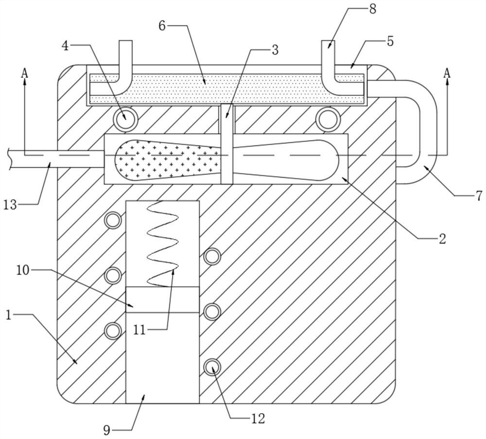
[0021] refer to Figure 1-2 , an LED lamp for a musical fountain, comprising a lamp housing 1, a plurality of LED lamp beads 4 of different colors are embedded in the lamp housing 1, a first circular groove 2 is opened on the side wall of the lamp housing 1, and a first circular groove 2 is opened in the lamp housing 1. A water inlet pipe 13 and a water outlet pipe 7 are fixedly connected to the side wall.

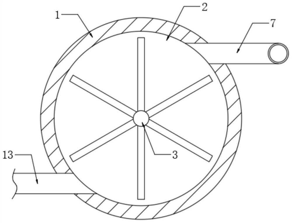
[0022] Specifically, the distribution positions of the water inlet pipe 13 and the water outlet pipe 7 on the lamp housing 1 are as follows: figure 2 As shown, this can ensure that when the fountain water flow enters the first circular groove 2, the water wheel 3 can be smoothly promoted to rotate.

[0023] And the water inlet pipe 13 and the water outlet pipe 7 are all connected with the inside of the first circular groove 2, and the bottom of the first circular groove 2 is rotatably connected with a water wheel 3. One of the blades of the water wheel 3 is made of iron,...

Embodiment 2

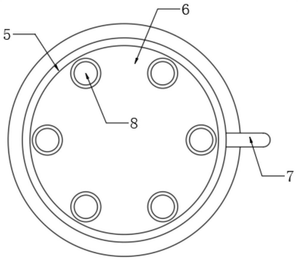
[0032] refer to Figure 4 , the difference from Embodiment 1 is that the side wall of the lamp housing 1 is fixedly connected with a return pipe 15, the water inlet end of the return pipe 15 is set on the upper end of the turntable 6, and the water outlet end of the return pipe 15 is set on the inner wall of the strip groove 9 and a first one-way valve 151 is installed in the return pipe 15 , and a through hole 14 is opened on the upper end of the slider 10 , and a second one-way valve 141 is installed in the through hole 14 .

[0033] Since the inner wall of the turntable 6 needs to fit closely with the inner wall of the second circular groove 5, and the fountain water flow needs to be discharged from the inner wall of the second circular groove 5 and enter the L-shaped pipe 8, the height of the turntable 6 A depth smaller than that of the second circular groove 5 is required. Therefore, when in use, water accumulation will occur on the rotating disk 6 .

[0034] In this em...


PUM


Abstract

The invention discloses an LED lamp for a music fountain, which comprises a lamp housing, a plurality of LED lamp beads of different colors are embedded in the lamp housing, and a first circular groove is opened on the side wall of the lamp housing. The side wall of the lamp housing is fixedly connected with a water inlet pipe and a water outlet pipe, and both the water inlet pipe and the water outlet pipe are connected with the inside of the first circular groove, and the bottom of the first circular groove is rotatably connected with a water wheel. One of the blades of the water wheel is made of iron, the side wall of the lamp housing is provided with a strip groove, and a slider made of magnetic material is slidably connected in the strip groove, and the lamp housing is embedded with a A helical coil, and both ends of the helical coil are coupled to a plurality of LED lamp beads. The present invention uses the water flow energy of the fountain to light up the LED lamp beads, which can ensure that the flickering frequency of the LED lamp beads is coordinated with the changing frequency of the water flow of the fountain, thereby greatly improving the landscape effect of the music fountain.

Description

technical field [0001] The invention relates to the technical field of equipment related to LED lamps, in particular to an LED lamp for a music fountain. Background technique [0002] The musical fountain is a movable fountain created for entertainment. It is designed according to aesthetics and often produces three-dimensional effects. LED lights are often installed in the musical fountain to achieve beautiful sound and light effects. [0003] Most of the lighting change effects of LED lights used in existing music fountains are controlled by electronic programs, and the water flow of the fountain is controlled by the power change of the water pump. Therefore, it is difficult to coordinate the dynamic change effect of the light with the change effect of the fountain, resulting in The landscape effect is average. In addition, it needs to transmit power to the water pump and LED lights at the same time, and the power consumption is relatively large. Contents of the inventio...

Claims


Application Information

Patent Timeline
Patent Type & Authority Patents(China)
IPC IPC(8): F21S9/04F21S10/06F21V23/00F21V33/00B05B17/08F21W121/02F21Y115/10
CPCB05B17/08F21S9/046F21S10/06F21V23/023F21V33/00F21W2121/02F21Y2115/10
Inventor 徐玲曹钰坤
Owner 中栩建设工程集团有限公司
Why Eureka
Try Eureka