Method and apparatus for driving switch apparatus

A switching device, a technology for driving switches, applied in relays, magnetic objects, electrical components, etc., can solve problems such as contact fouling, and achieve the effect of avoiding wear or pollution and cost realization.

Inactive Publication Date: 2011-04-06
SIEMENS AG
View PDF0 Cites 0 Cited by
  • Summary
  • Abstract
  • Description
  • Claims
  • Application Information

AI Technical Summary

Problems solved by technology

The downside of this solution is that the contacts of the switch can get dirty
In this case, as in the case described at the outset, the increased coil current is again supplied by the power supply with the above-mentioned possible disadvantageous consequences

Method used


Image

  • Method and apparatus for driving switch apparatus
  • Method and apparatus for driving switch apparatus
  • Method and apparatus for driving switch apparatus

Examples


Embodiment Construction

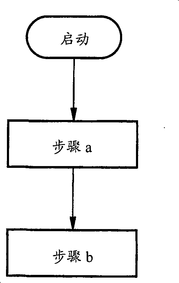
[0036] as in figure 1 As shown in the method according to the invention, the following two steps are basically carried out:

[0037] Step a) identifying a change in magnetic flux in the electromagnetic drive between a first position when the main contacts are open and a second position when the main contacts are closed, and

[0038] Step b) Limiting the coil current of the electromagnetic drive device to a predeterminable minimum current value in the second position when the change in magnetic flux exceeds a predetermined value.

[0039] In turn, a change in the magnetic flux is detected or measured when the armature of the electromagnetic drive moves and thus changes the magnetic circuit of the electromagnetic drive. As a result, a measurement-technological detection of the magnetic flux is achieved without contact.

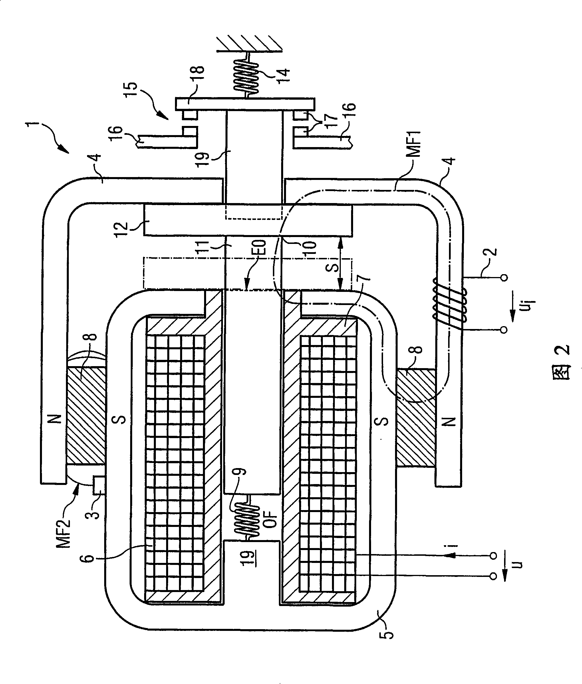
[0040] FIG. 2 shows a cross-sectional view of an embodiment of a device according to the invention with an electromagnetic drive device 1 supported by a perma...


PUM


Abstract

The invention relates to a method for operating a switching device using at least one electromagnetic drive (1), which has a displaceable armature (10) for opening and closing at least one main contact (15) of the switching device. According to the invention, a modification of the magnetic flux between a first position, when the main contact (15) is deactivated, and a second position, when the main contact (15) is activated, is identified in the electromagnetic drive (1) and a solenoid current (i) of the electromagnetic drive (1) is restricted to a predeterminable minimum current value in the second position, if the magnetic flux modification exceeds a predeterminable value. The great advantage of this is that an actuation displacement of the armature (10) can be identified as reliable, if an associated modification of the magnetic flux is also measured. The metrological recording of the magnetic flux is contactless.

Description

technical field [0001] The invention relates to a method for operating a switching device, and to a corresponding arrangement. Background technique [0002] By means of a switchgear, in particular a low-voltage switchgear, the current path between the power supply device and the load and thus its operating current can be switched on. This means that the connected load can be switched on and off safely by opening and closing the current path by the switching device. [0003] To complete the current path, low-voltage switching devices (e.g. contactors, circuit breakers or compact starters) have one or more so-called main contacts, which can be actuated by one or more control magnets or solenoids device to control. In this case, the main contact basically consists of a movable contact bridge and a fixed contact piece, to which the load and power supply are connected. To close and open the main contacts, the corresponding on or off signal is sent to the electromagnetic drive,...

Claims


Application Information

Patent Timeline
Patent Type & Authority Patents(China)
IPC IPC(8): H01H47/04
CPCH01H2047/046H01F7/1623H01F7/1805H01H47/04H01F7/1615
Inventor 弗里茨·波尔
Owner SIEMENS AG
Why Eureka
Try Eureka