Anti-loosening safety socket and plug

A technology for safety sockets and safety plugs, which is applied to the parts of the connection device, the device for joining/disconnecting the connection parts, and the two-part connection device, etc., which can solve the problems of high potential safety hazards of the socket, and achieve the purpose of avoiding electric shock and ensuring power consumption Effects of safety and protection circuits

Active Publication Date: 2020-08-11
杭州波普电器有限公司
View PDF10 Cites 5 Cited by
  • Summary
  • Abstract
  • Description
  • Claims
  • Application Information

AI Technical Summary

Problems solved by technology

[0005] The purpose of the present invention is to provide a safety socket and plug with high safety and anti

Method used


Image

  • Anti-loosening safety socket and plug
  • Anti-loosening safety socket and plug
  • Anti-loosening safety socket and plug

Examples


Example Embodiment

[0026] Example 1

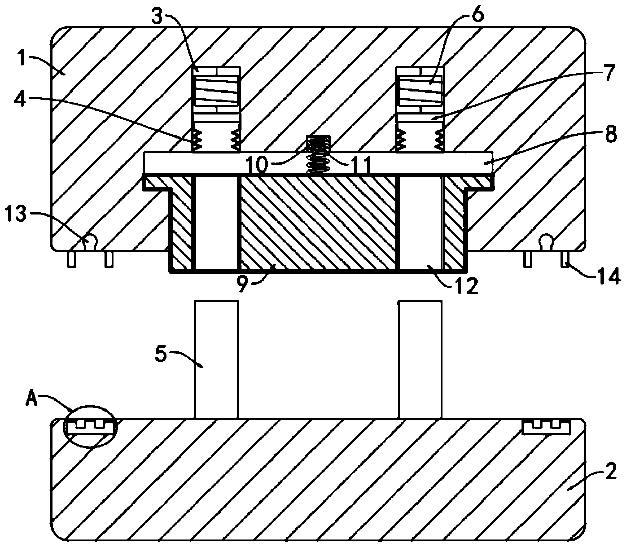
[0027] Such as Figure 1-2 As shown, an anti-loosening safety socket includes a base body 1, at least a pair of slots 3 are provided in the base body 1, and each slot 3 is provided with an elastic spring 4, the An inductance coil 6 is fixedly connected to the slot 3, and the inductance coil 6 can effectively avoid the impact of a sudden increase in current in the circuit on the electrical appliances, thereby protecting the electrical appliances.

[0028] One end of the inductor coil 6 is electrically connected to a conductive plate 7, and the conductive plate 7 and the inductor coil 6 are electrically connected in series on the circuit of the elastic reed 4, and the inductor coil 6 and the elastic reed 4 are respectively arranged on On the upper and lower ends of the conductive plate 7, a sliding groove 8 is provided on the side wall of the seat body 1, the inner bottom surface of the sliding groove 8 is connected to a plurality of slots 3, and a protective bloc...

Example Embodiment

[0037] Example 2

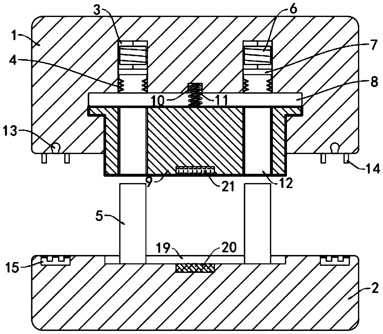
[0038] Such as image 3 As shown, the difference between this embodiment and embodiment 1 is that: the protective block 9 on the seat body 1 extends to the outside of the seat body 1, and the side wall of the insert box 2 is provided with a fixing groove 19 and a fixing groove 19 Match with guard block 9 (e.g. image 3 (Shown), a permanent magnet block 20 is fixedly embedded in the fixing groove 19, and a magnetic block 21 is fixedly embedded in the lower side wall of the protective block 9. The permanent magnet block 20 and the magnetic block 21 are positioned correspondingly and attract each other. It is worth mentioning that the return spring 11 is a memory spring.

[0039] In this embodiment, when the protective block 9 is completely moved into the sliding groove 8, part of the block is embedded in the fixing groove 19, which can increase the integrity of the connection when the socket and the plug are connected. When moving into the fixing slot 19, the perm...


PUM


Abstract

The invention belongs to the field of household appliances, and especially relates to an anti-loosening safety socket. The anti-loosening safety socket comprises a socket body, and at least one pair of slots is arranged in the seat body. An elastic reed is arranged in each slot; an inductance coil is fixedly connected in the slot; one end of the inductance coil is electrically connected with a conductive plate; the conductive plate and the inductance coil are electrically connected in series to the circuit of the elastic reed; the inductance coil and the elastic reed are arranged at the upperend and the lower end of the conductive plate respectively, a chute is formed in the side wall of the socket body, the inner bottom face of the chute is communicated with the multiple slots, a protection block is connected into the chute in a sliding mode, and a containing groove is formed in the inner bottom face of the chute. The inductance coil is connected to the circuit of the elastic reed inseries, when the pin is connected with the elastic reed, the inductance coil can generate an inductance phenomenon, so that the current on the circuit is gradually increased, the impact on an electric appliance caused by sudden increase of the current in the circuit can be effectively avoided, and the electric appliance is protected.

Description

technical field [0001] The invention belongs to the field of household electrical appliances, and in particular relates to a loose-proof safety socket and plug. Background technique [0002] Socket is a relatively common power supply device in daily life. It plays the role of connecting power supply and electrical appliances. It is often set in home life and work places, and will be set in different positions according to different usage requirements. [0003] In the process of inserting the electrical plug into most traditional sockets, once the front end of the pin touches the power supply, the pin will conduct current, but at this time the pin has not been fully inserted into the slot. If the operator accidentally touches the The exposed pins are very prone to electric shocks, which poses a great safety hazard. Moreover, most traditional sockets and pins are simply connected by the elastic reeds inside the slots. However, when the elastic reeds age When aging occurs over...

Claims


Application Information

Patent Timeline
IPC IPC(8): H01R13/502H01R13/62H01R13/627H01R13/629H01R24/00
CPCH01R13/502H01R13/6205H01R13/627H01R13/629H01R24/00
Inventor 冷辉张春丽
Owner 杭州波普电器有限公司
Why Eureka
Try Eureka