Self-moving type anti-seepage outdoor power distribution cabinet

A power distribution cabinet, self-moving technology, applied in substation/distribution device casing, electrical components, substation/switch layout details, etc. Stable operation and guaranteed cooling effect

Active Publication Date: 2020-08-11
奥宸科技有限公司
View PDF6 Cites 13 Cited by
  • Summary
  • Abstract
  • Description
  • Claims
  • Application Information

AI Technical Summary

Problems solved by technology

[0005] The purpose of the present invention is to provide a self-moving anti-seepage outdoor power distribution cabinet that prevents rainwater from penetrating into the box, aiming at the problem that rainwater is easy to penetrate into the box

Method used


Image

  • Self-moving type anti-seepage outdoor power distribution cabinet
  • Self-moving type anti-seepage outdoor power distribution cabinet
  • Self-moving type anti-seepage outdoor power distribution cabinet

Examples


Embodiment 1

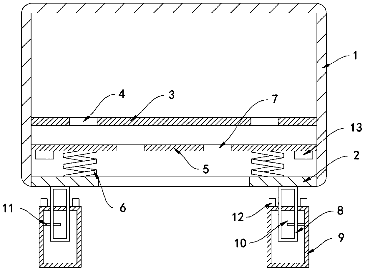
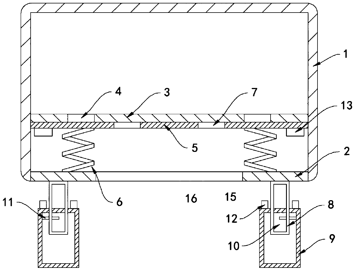
[0019] Such as Figure 1-2 As shown, a self-moving anti-seepage outdoor power distribution cabinet includes a cabinet body 1, the lower end of the cabinet body 1 is opened, and the side wall at the lower port of the cabinet body 1 is fixedly connected to the limit ring 2. Inside the cabinet body 1 A horizontally arranged bearing plate 3 is fixedly installed, and the electrical equipment is arranged on the bearing plate 3. A plurality of first heat dissipation holes 4 are equidistantly arranged in the bearing plate 3, and a horizontal lifting plate 5 is provided below the bearing plate 3 to lift The plate 5 is slidingly connected to the inner side wall of the cabinet body 1, and the lower end of the lifting plate 5 is fixedly connected to the limit ring 2 through the return spring 6. There are a plurality of second cooling holes 7 equidistantly arranged in the lifting plate 5, and the first cooling holes 4 and the second cooling holes 7 are alternately arranged.

[0020] The l...

Embodiment 2

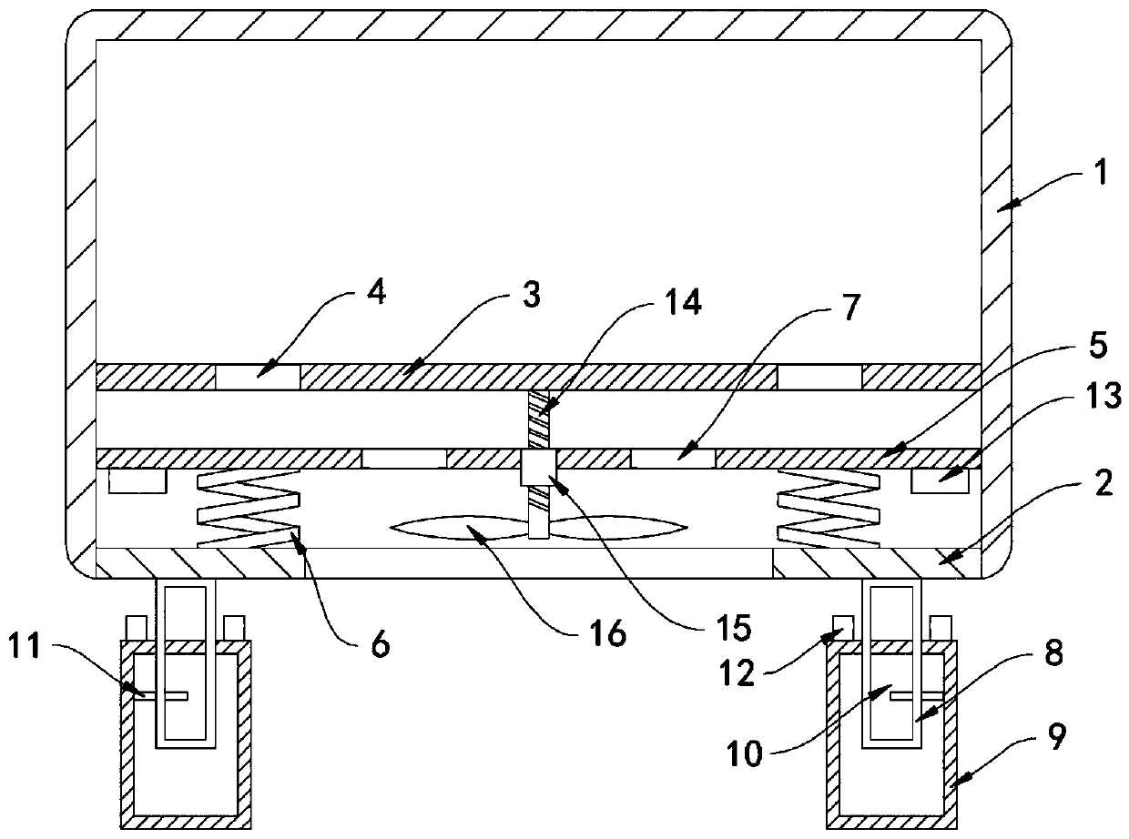
[0025] Such as image 3 As shown, the difference between this embodiment and Embodiment 1 is that: the lower surface of the bearing plate 3 is fixedly connected with a vertically arranged threaded rod 14, and the inside of the lifting plate 5 is fixedly provided with a threaded cylinder 15, and the lower end of the threaded rod 14 A fan 16 is coaxially mounted on the lower end of the threaded rod 14 through the threaded cylinder 15 and threadedly engaged with the threaded cylinder 15 .

[0026] In this embodiment, when there is no rainfall, the lifting plate 5 drives the threaded cylinder 15 to move downwards, thereby driving the threaded rod 14 and the rotation of the threaded rod 14, and the fan 16 rotates to push the outside air into the cabinet to enhance The heat dissipation effect of the power distribution cabinet, in rainy weather, the lifting plate 5 drives the threaded cylinder 15 to move upwards, and then drives the fan 16 to rotate in the opposite direction, generat...


PUM


Abstract

The invention belongs to the field of power distribution cabinets, and particularly relates to a self-moving type anti-seepage outdoor power distribution cabinet, which comprises a cabinet body, wherein an opening is formed in the lower end of the cabinet body, the side wall at the opening of the lower end of the cabinet body is fixedly connected with a limiting ring, a horizontally-arranged bearing plate is fixedly installed in the cabinet body, a plurality of first heat dissipation holes are distributed in the bearing plate at equal intervals, a horizontal lifting plate is arranged below thebearing plate, the lifting plate is slidably connected with the inner side wall of the cabinet body, the lower end of the lifting plate is fixedly connected with the limiting ring through a reset spring, a plurality of second heat dissipation holes are distributed in the lifting plate at equal intervals, the first heat dissipation holes and the second heat dissipation holes are distributed in a staggered mode, and the lower end of the cabinet body is fixedly connected with two supporting frames. According to the invention, the height of the cabinet body can be automatically adjusted accordingto the external temperature, so that the windproof capability is good, the problem that rainwater permeates into the cabinet body from the bottom in rainy days is avoided, and the reliable and stableoperation of the power distribution cabinet is ensured.

Description

technical field [0001] The invention belongs to the field of power distribution cabinets, in particular to a self-moving anti-seepage outdoor power distribution cabinet. Background technique [0002] Power distribution cabinets can be divided into power distribution cabinets, lighting distribution cabinets, metering cabinets and other final-level equipment of power distribution systems. They are mainly used in power plants, substations, petrochemicals, metallurgical rolling steel, light industry textiles, factories and mines, and residential quarters. , high-rise buildings and other different occasions. [0003] There are outdoor power distribution cabinets installed on both sides of the road in the city to supply the city's electricity demand. Air intake grilles are set on the side walls of the outdoor power distribution cabinets for ventilation and heat dissipation. In rainy days, rainwater can easily enter through the air intake grilles. In the cabinet, and when the amou...

Claims


Application Information

Patent Timeline
Patent Type & Authority Applications(China)
IPC IPC(8): H02B1/56H02B1/50H02B1/30H02B1/54
CPCH02B1/303H02B1/505H02B1/54H02B1/565
Inventor 韩世朗
Owner 奥宸科技有限公司
Why Eureka
Try Eureka