
Transmission speed difference steering device for vehicle

A technology of steering device and speed difference, applied in the direction of non-deflectable wheel steering, steering mechanism, vehicle components, etc., can solve the problems of low running speed, maintenance, speed difference, etc.

Inactive Publication Date: 2020-08-14
SHANDONG VOCATIONAL COLLEGE OF SCI & TECH
View PDF13 Cites 7 Cited by
  • Summary
  • Abstract
  • Description
  • Claims
  • Application Information

AI Technical Summary

Problems solved by technology

However, in this application, since a two-way variable-displacement hydraulic pump is used to control the speed of the double crawlers, there is a speed difference in the operation of the double crawlers during the steering process, and the speed difference depends on the speed of the fixed-displacement hydraulic motor. The speed of the fixed-displacement hydraulic motor depends on the flow of the two-way variable-displacement hydraulic pump, and the flow of the two-way variable-displacement hydraulic pump is too large to damage the pump body. The running speed of the track will not be the same, so the turning radius will be larger, and in the process of turning, because the running speed of one side of the track is high, the running speed of the other side of the track is small, which will cause the track on the side with a smaller running speed Severe friction will reduce the service life of the track on this side, and it will also cause the walking wheel to detach from the track during the steering process, resulting in unnecessary maintenance
[0003] In summary, there are obviously inconveniences and defects in the actual use of the existing technology, so it is necessary to improve

Method used


Image

  • Transmission speed difference steering device for vehicle
  • Transmission speed difference steering device for vehicle
  • Transmission speed difference steering device for vehicle

Examples


Embodiment Construction

[0018] In order to make the objectives, technical solutions, and advantages of the present invention clearer, the following further describes the present invention in detail with reference to the accompanying drawings and embodiments. It should be understood that the specific embodiments described here are only used to explain the present invention and are not used for Limit the invention.

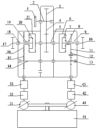
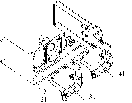
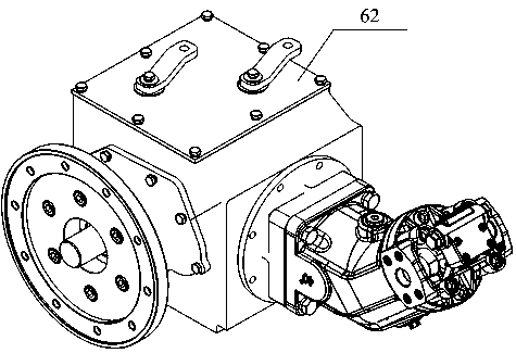
[0019] See Figure 1~3 , The present invention provides a vehicle transmission speed difference steering device, including a control device, a steering device and a walking device. The control device is connected to the walking device through the steering device, and the control device is used to control the steering device so that it can drive The walking device realizes in-situ steering, reduces steering time and improves steering efficiency. The steering device includes a gear box 51, a pump body, a gearbox, and a motor. The pump body, gearbox, and motor are all two in number. The two pum...


PUM


Abstract

The invention is applicable to the technical field of vehicle power transmission and provides a transmission speed difference steering device for a vehicle. The device comprises a control device, a steering device and a walking device, wherein the control device is connected with the walking device through the steering device, the steering device includes gear boxes, at least two pump bodies, at least two speed changing boxes and at least two motors, the gear boxes are connected with the pump bodies through connecting pieces, and the motors are opposite in rotating direction and connected withthe walking device through transmission shafts. Therefore, crawler belts on two sides can be controlled at the same time, the two crawler belts achieve reverse synchronous operation, and a tracked vehicle rotates in situ.

Description

Technical field [0001] The invention relates to the technical field of vehicle power transmission, in particular to a vehicle transmission speed difference steering device. Background technique [0002] The crawler walking mechanism is widely used in construction machinery, tractors and other field operation vehicles. The poor walking conditions require the walking mechanism to have sufficient strength and rigidity, as well as good running and turning capabilities. The track is in contact with the ground, and the driving wheel is not in contact with the ground. When the motor drives the drive wheel to rotate, the drive wheel continuously rolls up the crawler belt from the rear through the meshing between the gear teeth on the drive wheel and the crawler chain under the action of the drive torque of the reducer. The part of the crawler that touches the ground gives the ground a backward force, and the ground correspondingly gives the crawler a forward reaction force. This reacti...

Claims


Application Information

Patent Timeline
IPC IPC(8): B62D11/04
CPCB62D11/04
Inventor 武莹王珂
Owner SHANDONG VOCATIONAL COLLEGE OF SCI & TECH
Learn More