Complete machine in-situ swivel device and swivel method of bridge girder erection machine

A bridge erecting machine, in-situ technology, applied in the field of in-situ turning head device of the bridge erecting machine, can solve the problems of time-consuming, labor-intensive and time-consuming, etc., and achieve the effect of cost saving, high efficiency and flexible rotation

Pending Publication Date: 2020-11-17
CHINA RAILWAY FIRST GRP CO LTD +1
View PDF0 Cites 1 Cited by
  • Summary
  • Abstract
  • Description
  • Claims
  • Application Information

AI Technical Summary

Problems solved by technology

There are two more primitive methods: 1. Disassemble into parts, turn them around one by one, and then assemble them one by one; it takes at least a week, which is labor-intensive and time-consuming; 2. Level a large square with a diameter of 100 meters and organize two It ta

Method used


Image

  • Complete machine in-situ swivel device and swivel method of bridge girder erection machine
  • Complete machine in-situ swivel device and swivel method of bridge girder erection machine
  • Complete machine in-situ swivel device and swivel method of bridge girder erection machine

Examples


Example Embodiment

[0048] Embodiments of the present invention will be described in more detail below with reference to the accompanying drawings. While certain embodiments of the invention are shown in the drawings, it should be understood that the invention may be embodied in various forms and should not be construed as limited to the embodiments set forth herein, but rather are provided for the purpose of A more thorough and complete understanding of the present invention. It should be understood that the drawings and embodiments of the present invention are only used for exemplary purposes, and are not used to limit the protection scope of the present invention.

[0049] It should be noted that the concepts such as first and second mentioned in the present invention are only used to distinguish different devices, modules or units, and are not used to limit the order or interdependence of the functions performed by these devices, modules or units .

[0050] It should be noted that the direc...


PUM


Abstract

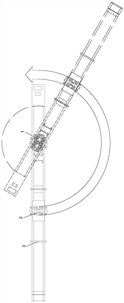
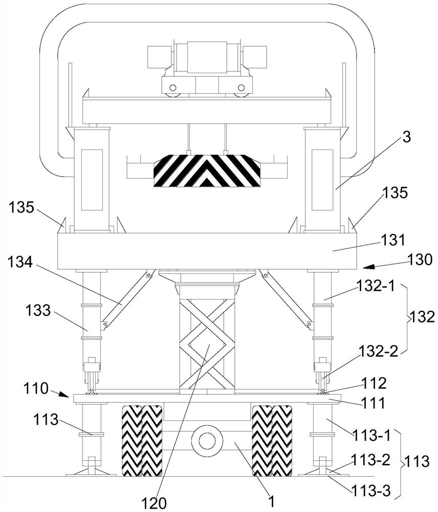
The invention discloses a complete machine in-situ swivel device of a bridge girder erection machine, which comprises a first carrier loader, a second carrier loader, a first bridge girder erection machine carrying frame and a second bridge girder erection machine carrying frame, the first bridge girder erection machine carrying frame comprises a fixed part, a connecting part and a rotating part;the connecting part is arranged between the fixed part and the rotating part and used for supporting and rotationally connecting the rotating part to the upper portion of the fixed part, the upper endof the connecting part is fixedly connected with the rotating part, and the rotating part can rotate around the central axis of the connecting part relative to the fixed part. The second bridge girder erection machine carrying frame is mounted on the second carrying vehicle and used for carrying one end of the bridge girder erection machine, so that the bridge girder erection machine rotates around the central axis of the connecting part under the support of the first bridge girder erection machine carrying frame and the carrying of the second bridge girder erection machine carrying frame. During steering, the whole bridge girder erection machine rotates, disassembly and reassembly are not needed, the labor intensity of field staff is relieved, and the cost for renting hoisting equipmentis saved.

Description

technical field [0001] The invention relates to the technical field of bridge erection construction, in particular to an in-situ rotating head device and a rotating head method of a complete bridge erecting machine. Background technique [0002] Because the JQL185 bridge erection machine can replace the traditional "track change method" laying operation, it realizes the purpose of laying the seamless line at one time, reduces the construction cost and improves the construction efficiency. Over the past few years, it has been more and more popular among paving construction units and construction units. [0003] However, due to its structural characteristics, the bridge can only be bridged forward in one direction. When encountering the construction of seamless line laying with many points and long lines, it is necessary to constantly turn around. There are two more primitive methods: 1. Disassemble into parts, turn them one by one, and then assemble them one by one; it take...

Claims


Application Information

Patent Timeline
IPC IPC(8): E01D21/00
CPCE01D21/00
Inventor 高亚文冯斌杨云堂胡达李子峰孙柏辉杨帆张永成徐岗陈智广胡海涛范福贵
Owner CHINA RAILWAY FIRST GRP CO LTD
Why Eureka
Try Eureka