Flap and rotor wing linked tilting mechanism

A technology of tilting mechanism and rotor tilting, which is applied in the directions of rotorcraft, motor vehicles, transportation and packaging, etc., can solve the problems such as the deceleration requirements of the whole machine without considering the aerodynamic performance of the rotor tilting, and the quality minimization of the overall scheme is not considered, etc. Achieve the effect of increasing resistance, increasing stability and reducing costs

Active Publication Date: 2021-04-30
ZHEJIANG LAB
View PDF6 Cites 0 Cited by
  • Summary
  • Abstract
  • Description
  • Claims
  • Application Information

AI Technical Summary

Problems solved by technology

This scheme only considers the tilting system as an independent device, without considering the combination of the components of the wing itself to minimize the mass of the overall solution, and at the same time, it does not consider the aerodynamic performance before and after the rotor tilts and the need for deceleration of the whole machine

Method used


Image

  • Flap and rotor wing linked tilting mechanism
  • Flap and rotor wing linked tilting mechanism
  • Flap and rotor wing linked tilting mechanism

Examples


Embodiment 1

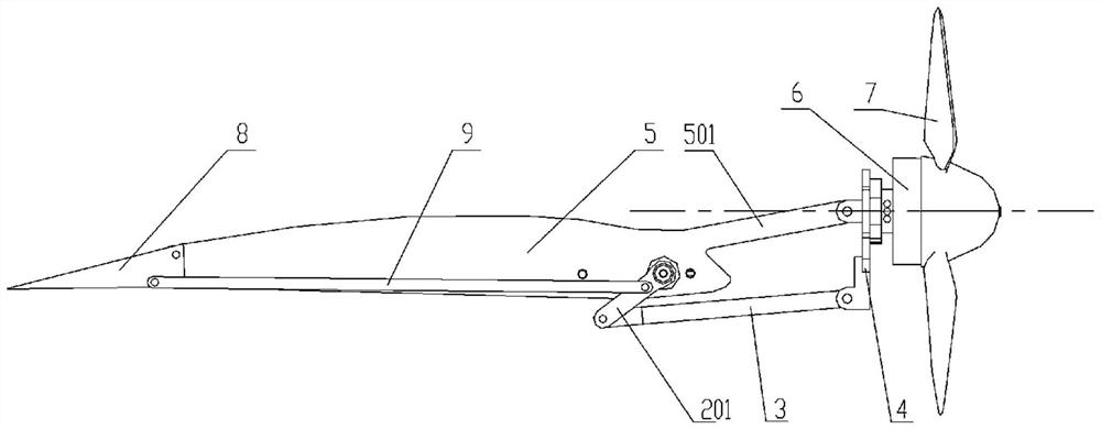
[0035] Such as Figure 1 ~ Figure 3A flap-rotor linkage tilting mechanism shown includes a steering gear 101, a steering gear arm 201, a connecting rod 3, a rotor motor base 4, a rib 5 as a bracket, and a flap connecting rod 9, for convenience Describe present embodiment, show rotor 7 and flap keel 8 simultaneously among the figure, described wing rib 5 is provided with support arm 501, and described support arm 501 is arranged on the plane where chord line is located (due to present embodiment The main part of the wing rib 5 is the equidistant offset line of the wing interface profile, so it is easy to judge the chord line position of the wing), the steering arm 201 and the rotor connecting rod 3, the rotor connecting rod 3 and the rotor Motor seat 4, rotor motor seat 4 and support arm 501, flap keel 8 and wing rib 5, flap connecting rod 9 and flap keel 8 and steering gear arm 201 are all connected by rotating shaft rotation, and described steering gear 101 is fixed On the w...

Embodiment 2

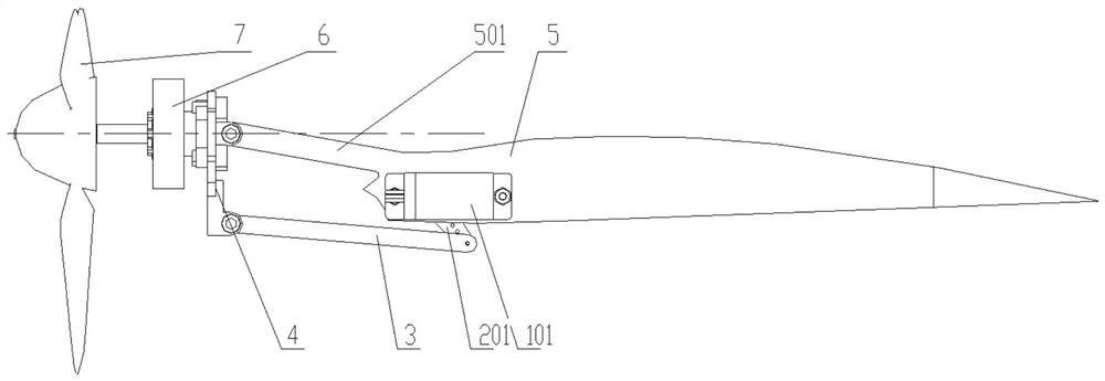
[0038] Such as Figure 4 with 5 As shown, the present embodiment is an application case of Embodiment 1. On the basis of Embodiment 1, a wing 10 is added (only a part is shown in the figure), and the wing 10 is provided with a swing arm groove 1001 and a support Arm hole 1002 , the main part of the rib 5 is fixed inside the wing 10 , the support arm 501 extends out of the wing 10 through the support arm hole 1002 , and the steering arm 201 extends out of the wing through the swing arm groove 1001 .

Embodiment 3

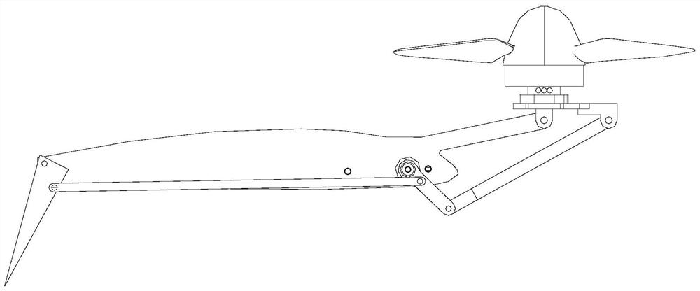
[0040] Such as Figure 6 ~ Figure 8 The shown air-driven tilting mechanism of a rotor and flap linkage includes a cylinder 102, a relay rod 202, a rotor connecting rod 3, a rotor motor seat 4, a rib 5 as a bracket and a flap connecting rod 9, which is Conveniently describe present embodiment, show rotor 7, flap keel 8 simultaneously among the figure, described wing rib 5 is provided with support arm 501, and described support arm 501 is arranged on the plane where chord line is located (because in this embodiment The main part of the wing rib 5 is the equidistant offset line of the wing interface profile, so it is easy to judge the chord line position of the wing), the cylinder 102 and the wing rib 5, the cylinder 102 and the rotor motor seat 4, Rotor motor seat 4 and support arm 501, flap keel 8 and wing rib 5, flap connecting rod 9 and flap keel 8, relay rod 202 and flap connecting rod 9, relay rod 202 and rotor connecting rod 3, The rotor connecting rod 3 and the rotor mot...


PUM


Abstract

The invention discloses a flap and rotor wing linked tilting mechanism, which solves problems of lack of flap and rotor wing linkage and aerodynamic force consideration; a bracket is fixed on a wing, two ends of the bracket are respectively and movably connected with a flap keel and a rotor wing assembly arranged on the wing, and the rotor wing assembly comprises a rotor wing motor and a rotor wing motor seat. The rotor wing motor is fixedly arranged on the rotor wing motor seat, and the rotor wing motor seat is movably connected with the bracket. A rotor wing tilting mechanism is connected with the bracket and the rotor wing assembly and used for driving the rotor wing assembly to tilt around the bracket. And a flap linkage mechanism is connected with the rotor wing tilting mechanism and the bracket, and is used for linking the flaps to swing when the rotor wing assembly tilts. When the axis of the rotor wing is in a horizontal state, the flap is in a non-working state, and when the axis of the rotor wing is converted into a vertical state from the horizontal state, flap linkage is changed into lower hem, so that the purposes of linkage of the tilting mechanism and the flap and optimization of aerodynamic layout are achieved.

Description

technical field [0001] The invention relates to the field of tilting multi-rotor aircraft, in particular to a tilting mechanism with flaps and rotors linked. Background technique [0002] Conventional rotorcraft (such as helicopters, multi-rotor drones, etc.) have relatively efficient vertical take-off and landing performance, hovering, low-altitude and low-speed flight, and unique backward and side flight capabilities. Asymmetric, its maximum flight speed is limited by the compressibility of the airflow of the forward blades and the separation of the airflow of the backward blades, so it is difficult to further increase the flight speed. Tilting multi-rotor aircraft has the characteristics of efficient hovering performance, high-speed cruising capability, long range, long endurance, high safety, environmental protection, and low noise. It is a feasible development direction for new configuration rotor aircraft in the future, but The tilting mechanism requires an additional...

Claims


Application Information

Patent Timeline
Patent Type & Authority Applications(China)
IPC IPC(8): B64C27/52
CPCB64C27/52
Inventor 谢安桓陈令凯娄斌严旭飞张丹朱世强
Owner ZHEJIANG LAB
Why Eureka
Try Eureka