
Light emitting diode device and control method thereof

A technology of light-emitting diodes and control methods, which is applied to instruments, static indicators, etc., can solve the problems of display quality impact, afterimage, and insufficient response time, and achieve the effects of improving display quality, reducing dynamic afterimage, and improving response time

Inactive Publication Date: 2020-08-14
AU OPTRONICS CORP
View PDF12 Cites 2 Cited by
  • Summary
  • Abstract
  • Description
  • Claims
  • Application Information

AI Technical Summary

Problems solved by technology

[0003] However, when the active matrix organic light-emitting diodes operate at high speed, when the display screen is switching, motion blur and insufficient response time usually occur, so that during the screen switching process There will be some afterimages in the image, which will affect the overall display quality

Method used

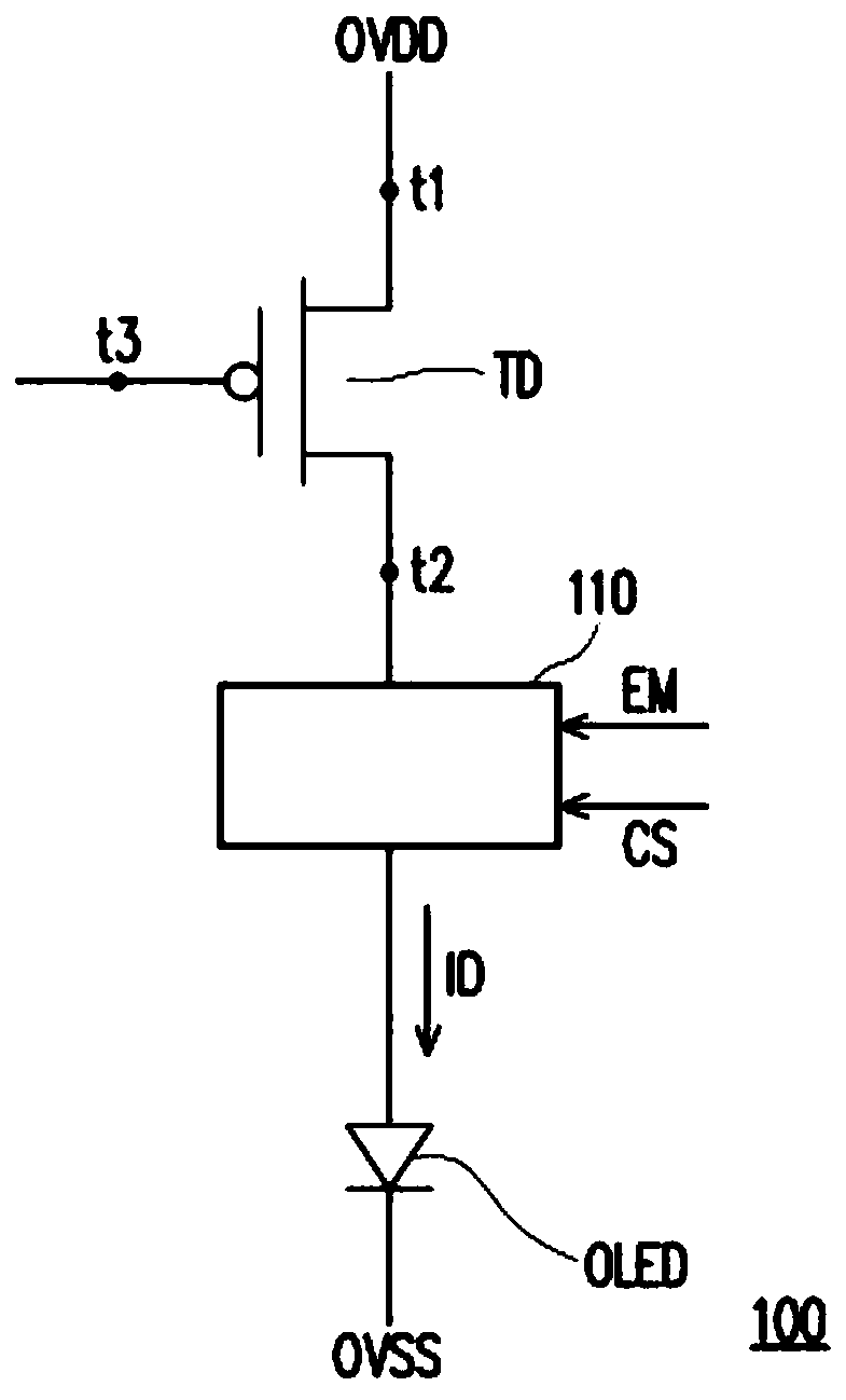
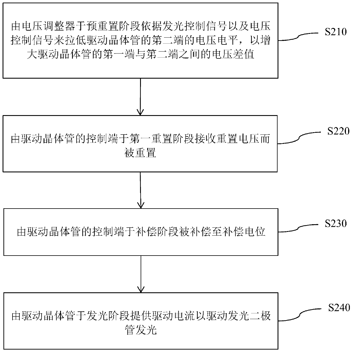
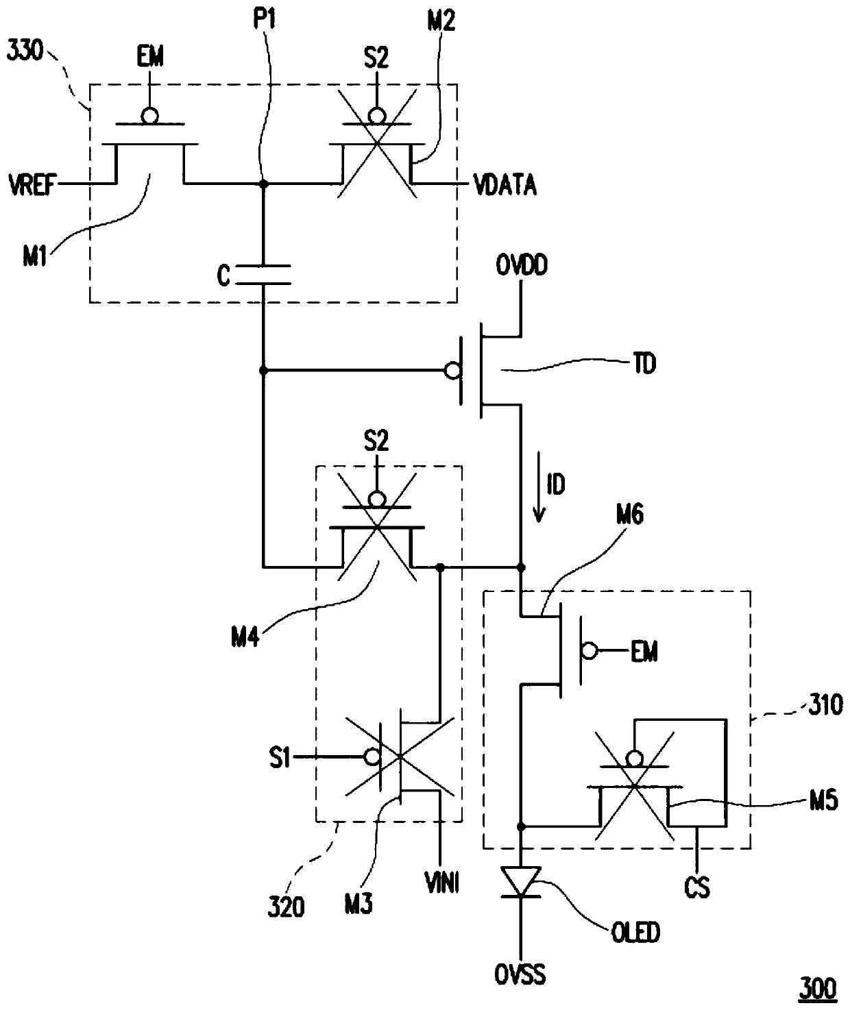

Image

  • Light emitting diode device and control method thereof
  • Light emitting diode device and control method thereof
  • Light emitting diode device and control method thereof

Examples


Embodiment Construction

[0056] Below in conjunction with accompanying drawing, structural principle and working principle of the present invention are specifically described:

[0057] As used throughout this specification, including the claims, the term "coupled (or connected)" may refer to any direct or indirect means of connection. For example, if it is described that a first device is coupled (or connected) to a second device, it should be interpreted that the first device can be directly connected to the second device, or the first device can be connected to the second device through other devices or certain A connection means indirectly connected to the second device. In addition, wherever possible, elements / components / steps using the same reference numerals in the drawings and embodiments represent the same or similar parts. Elements / components / steps using the same symbols or using the same terms in different embodiments can refer to related descriptions.

[0058] figure 1 It is a schematic ...


PUM


Abstract

The invention provides a light emitting diode device and a control method thereof. The control method comprises the following steps: a voltage regulator lowers the voltage potential of the second endof a driving transistor in a pre-reset stage according to a light-emitting control signal and a voltage control signal so as to increase the voltage difference between the first end and the second endof the driving transistor; the control end of the driving transistor receives the reset voltage in a first reset stage to be reset; the control end of the driving transistor is compensated to a compensation potential in a compensation stage; and the driving transistor provides a driving current at a light-emitting stage to drive the light-emitting diode to emit light.

Description

technical field [0001] The invention relates to a light emitting diode device and a control method of the light emitting diode device. Background technique [0002] With the advancement of display technology, light-emitting diodes have been widely used in display technology, and Active-Matrix Organic Light-Emitting Diode (AMOLED) is one of the main development focuses of display technology. [0003] However, when the active matrix organic light-emitting diodes operate at high speed, when the display screen is switching, motion blur and insufficient response time usually occur, so that during the screen switching process There will be some afterimages in the video, which will affect the overall display quality. Therefore, how to effectively improve or reduce the display condition of image sticking through appropriate control methods, and further improve the response time of image switching, so as to improve the overall display quality, will be an important subject for those ...

Claims


Application Information

Patent Timeline
Patent Type & Authority Applications(China)
IPC IPC(8): G09G3/3208
CPCG09G3/3208G09G3/3233G09G2300/0819G09G2300/0842G09G2300/0861G09G2300/0866G09G2310/0251G09G2320/0257G09G3/3291G09G2310/0272G09G2310/061
Inventor 洪森全
Owner AU OPTRONICS CORP
Learn More