
Back projection brightness control unit based on automatic detection

A technology of brightness control and automatic detection, applied in the direction of cathode ray tube indicators, instruments, static indicators, etc., can solve the problems of dynamic afterimages, large power consumption, poor perception of dark images, etc., to increase dynamic Contrast, reduce light leakage, save power consumption

Inactive Publication Date: 2017-03-15
江苏清投视讯科技有限公司
View PDF3 Cites 4 Cited by
  • Summary
  • Abstract
  • Description
  • Claims
  • Application Information

AI Technical Summary

Problems solved by technology

However, when the ambient light is bright, the pupils of the human eye will shrink, and the perception of dark images is poor. Unclear problem, this is because the existing dynamic backlight adjustment method does not take into account the influence of ambient light, and needs to be improved
Moreover, the existing rear projection brightness control unit has the disadvantages of large power consumption, light leakage and dynamic afterimage, which need to be further improved

Method used


Image

  • Back projection brightness control unit based on automatic detection

Examples


Embodiment 1

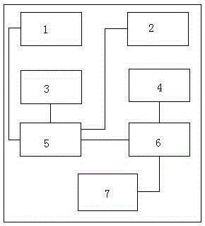
[0014] Embodiment 1: A rear projection brightness control unit based on automatic detection, including a dynamic backlight adjustment unit 1, an ambient light detection unit 2, a man-machine interface unit 3, a backlight calculation unit 4, a timing control unit 5, and a pulse width modulation unit 6 , the pulse width modulation unit 6 is coupled to the backlight calculation unit 4 and the timing control unit 5, the timing control unit 5 is coupled to the backlight adjustment unit 1, the ambient light detection unit 2, and the man-machine interface unit 3, and the pulse width modulation unit 6 is further coupled to A backlight driving unit 7 . The dynamic backlight adjustment unit 1 is used to receive an image signal, and generate a dynamic backlight control signal according to the image signal; the ambient light detection unit 2 is used to detect ambient light, and generate an ambient light reference signal according to the ambient light; the man-machine The interface unit 3 ...


PUM


Abstract

The invention provides a back projection brightness control unit based on automatic detection. The back projection brightness control unit includes a dynamic backlight regulation unit, an ambient light detection unit, a man-machine interface unit, a backlight arithmetic unit, a time sequence control unit and a pulse width modulation unit, wherein the pulse width modulation unit is coupled to the backlight arithmetic unit and the time sequence control unit, the time sequence control unit is coupled with the backlight regulation unit, the ambient light detection unit and the man-machine interface unit, and the pulse width modulation unit is additionally coupled with a backlight drive unit. Power consumption is saved, light leak is reduced and dynamic contrast is increased, redundant power consumption can also be reduced and dynamic ghost generated by state switching can be reduced.

Description

technical field [0001] The invention relates to the technical field of video image processing, in particular to core technology algorithms such as image shrink, zoom, and overlay. Background technique [0002] Splicing image controller is also called image processor, multi-screen splicer, etc. Its main function is to divide a complete image signal into multiple signals, distribute them to multiple display units, and form a large display screen to display dynamic images at the same time. It is suitable for network operation centers, public control centers, intelligent traffic management centers, processing centers, civilian or military surveillance systems, call centers, financial centers, video conference rooms, etc. However, when the ambient light is bright, the pupils of the human eye will shrink, and the perception of dark images is poor. The problem is not clear. This is because the existing dynamic backlight adjustment method does not take the influence of ambient ligh...

Claims


Application Information

Patent Timeline
Patent Type & Authority Applications(China)
IPC IPC(8): G09G5/10
Inventor 王展高玉斌邢思原章倩陈欢
Owner 江苏清投视讯科技有限公司
Learn More