Building stone cutting equipment
A technology for stone cutting and construction. It is applied in stone processing equipment, stone processing tools, metal processing equipment, etc. It can solve the problems that affect the strength of stone mechanisms, there is no stone cutting equipment, and crystalline silica cannot be cleaned effectively.
- Summary
- Abstract
- Description
- Claims
- Application Information
AI Technical Summary
Problems solved by technology
Method used
Image
Examples
specific Embodiment approach 1
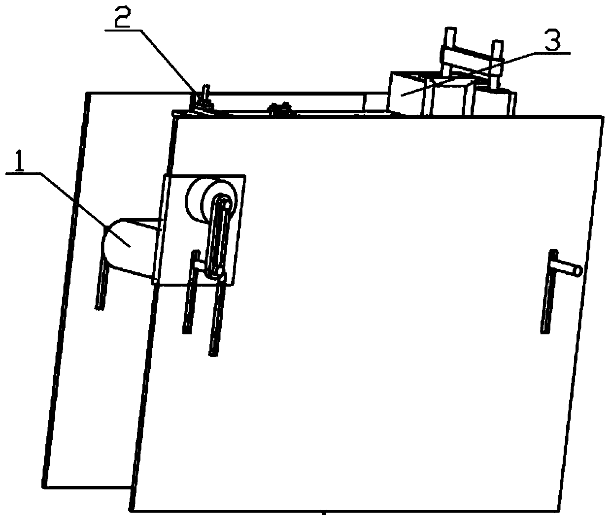
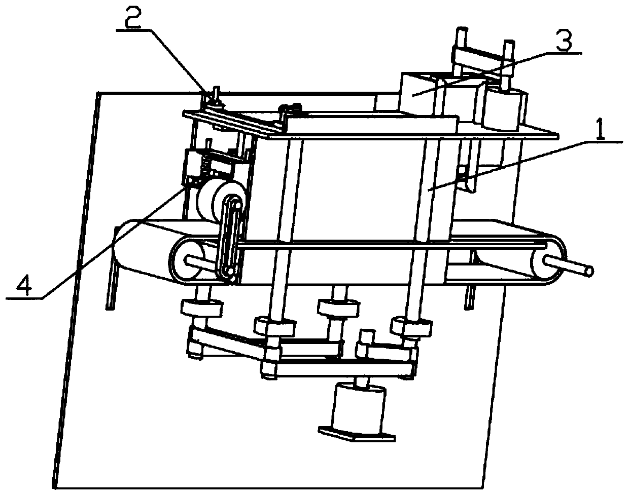
[0034] Combine below figure 1 , figure 2 , image 3 , Figure 4 , Figure 5 , Image 6 , Figure 7 , Figure 8 , Figure 9 , Figure 10 , Figure 11 , Figure 12 , Figure 13 , Figure 14 , Figure 15 , Figure 16 , Figure 17 , Figure 18 To illustrate this embodiment, the present invention relates to a stone cutting device, more specifically a stone cutting device for construction, including a transmission and lifting mechanism 1, a longitudinal movement mechanism 2, a stone cleaning mechanism 3, a stone cutting mechanism 4, and the equipment The stone can be transported, the equipment can adjust the relative height of the stone, the equipment can clean the crystalline silica attached to the surface of the stone, and the equipment can cut the stone into a specified shape.
[0035] The transmission and lifting mechanism 1 is connected with the vertical movement mechanism 2, the vertical movement mechanism 2 is connected with the stone cleaning mechanism 3, th...
specific Embodiment approach 2
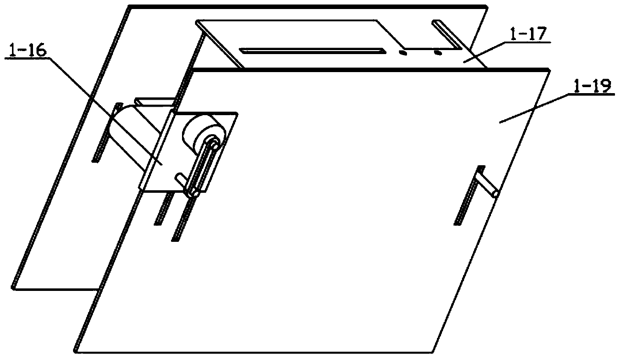
[0037] Combine below figure 1 , figure 2 , image 3 , Figure 4 , Figure 5 , Image 6 , Figure 7 , Figure 8 , Figure 9 , Figure 10 , Figure 11 , Figure 12 , Figure 13 , Figure 14 , Figure 15 , Figure 16 , Figure 17 , Figure 18 Describe this embodiment, this embodiment will further explain the first embodiment, the transmission and lifting mechanism 1 includes a transmission motor 1-1, a transmission motor shaft 1-2, a transmission belt a1-3, a transmission shaft a1-4, a transmission belt Rotary shaft 1-5, conveyor belt 1-6, lifting motor 1-7, lifting motor shaft 1-8, driving belt b1-9, driving screw shaft 1-10, driving belt c1-11, driving belt d1-12, displacement Plate 1-13, displacement connection plate 1-14, ascending motor mounting plate 1-15, transmission motor mounting block 1-16, transmission equipment plate 1-17, screw connection block 1-18, equipment installation side plate 1-19, The transmission motor 1-1 is connected with the transmissi...
specific Embodiment approach 3
[0039] Combine below figure 1 , figure 2 , image 3 , Figure 4 , Figure 5 , Image 6 , Figure 7 , Figure 8 , Figure 9 , Figure 10 , Figure 11 , Figure 12 , Figure 13 , Figure 14 , Figure 15 , Figure 16 , Figure 17 , Figure 18 Describe this embodiment, this embodiment will further explain the first embodiment, the described longitudinal movement mechanism 2 includes a longitudinal power motor 2-1, a longitudinal motor shaft 2-2, a belt 2-3, a power transmission shaft 2-4, a limiter Bit plate 2-5, moving gear 2-6, mounting plate a2-7, cross plate 2-8, equipment mounting block 2-9, pulley mechanism 2-10, rack 2-11, longitudinal equipment mounting plate 2-12 , The motor mounting plate 2-13, the longitudinal power motor 2-1 is connected with the longitudinal motor shaft 2-2, the longitudinal motor shaft 2-2 is frictionally connected with the belt 2-3, and the belt 2-3 is frictionally connected with the power transmission shaft 2-4 , the power transmi...
PUM
 Abstract
Description
Claims
Application Information
 - R&D
- Intellectual Property
- Life Sciences
- Materials
- Tech Scout
- Unparalleled Data Quality
- Higher Quality Content
- 60% Fewer Hallucinations
Browse by: Latest US Patents, China's latest patents, Technical Efficacy Thesaurus, Application Domain, Technology Topic, Popular Technical Reports.
© 2025 PatSnap. All rights reserved.Legal|Privacy policy|Modern Slavery Act Transparency Statement|Sitemap|About US| Contact US: help@patsnap.com


