
Air-fuel ratio control method reflecting brake booster inflow flow rate

A technology of brake booster and air-fuel ratio, applied in the direction of brake, engine control, fuel injection control, etc., can solve problems such as preventing misfire, achieve stable air-fuel ratio control, suppress the occurrence of misfire, and reduce the problem of exhaust gas Effect

Pending Publication Date: 2020-08-18
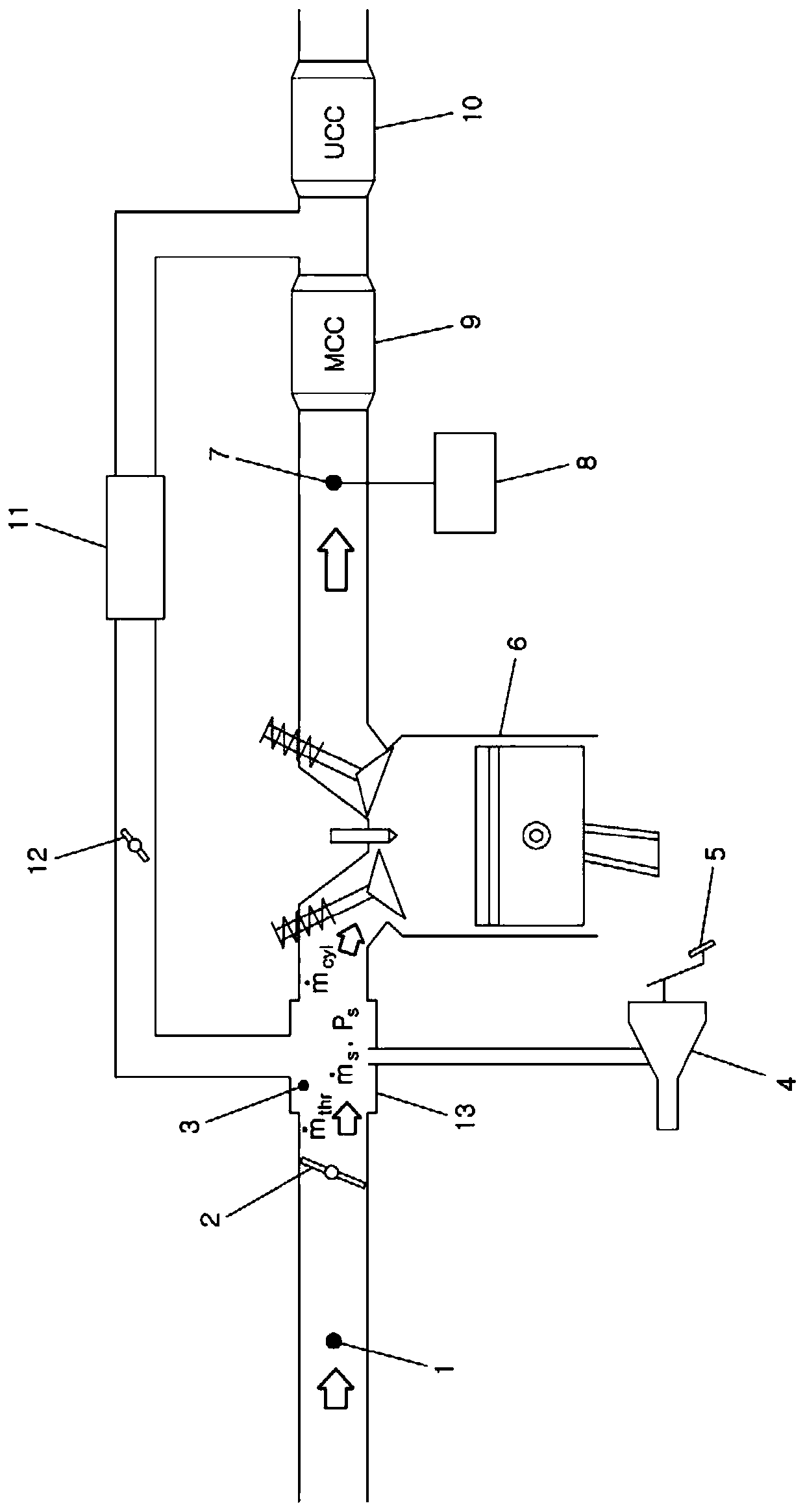
HYUNDAI MOTOR CO LTD +1
View PDF10 Cites 0 Cited by
  • Summary
  • Abstract
  • Description
  • Claims
  • Application Information

AI Technical Summary

Problems solved by technology

However, the applicant found that: when a large amount of fresh air components flow in from the brake booster 4, it will become a lean state in which the value of the air-fuel ratio exceeds a predetermined limit value (for example, 1.5), and the feedback control of the lambda control unit 8 stops. , so it is also difficult to prevent misfire by λ control

Method used


Image

  • Air-fuel ratio control method reflecting brake booster inflow flow rate
  • Air-fuel ratio control method reflecting brake booster inflow flow rate
  • Air-fuel ratio control method reflecting brake booster inflow flow rate

Examples


Embodiment Construction

[0037] The following description is merely exemplary in nature and is not intended to limit the invention, application or uses. It should be understood that throughout the drawings, corresponding reference numerals indicate like or corresponding parts and features.

[0038] However, detailed descriptions of known functions and configurations that may unnecessarily obscure the subject matter of the present invention will be omitted.

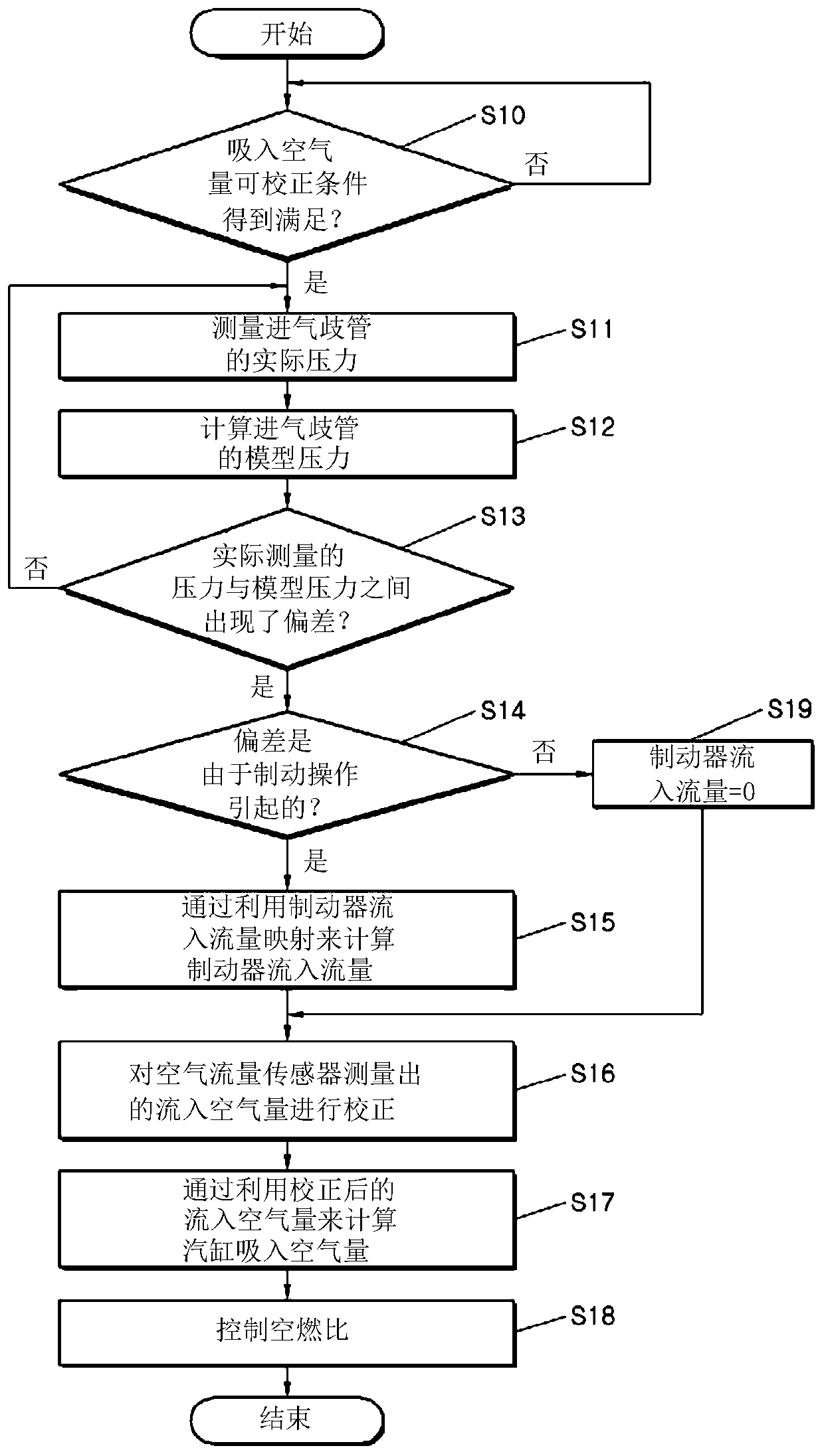
[0039] figure 2 is a flowchart showing an air-fuel ratio control method according to an embodiment of the present invention.

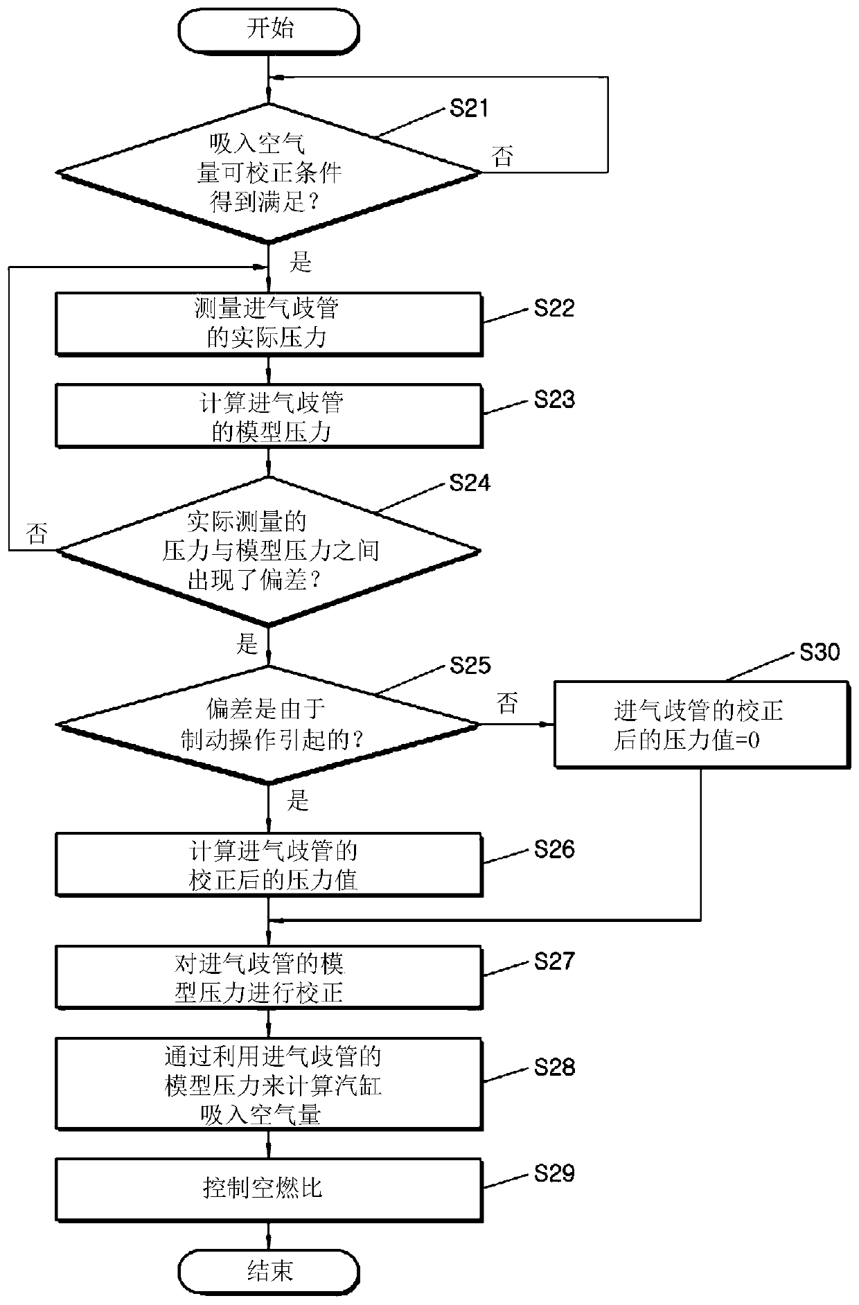
[0040] Such as figure 2 As shown, when the air-fuel ratio control method is executed, it is firstly determined in step S10 whether the intake air amount correctable condition has been satisfied. The intake air amount correctable condition is a condition for determining whether or not it is an operating state of the engine suitable for applying the air amount flowing into the intake manifold 13 from the brake booster 4...


PUM


Abstract

The invention relates to an air-fuel ratio control method reflecting a brake booster inflow flow rate, and the method includes the steps: determining a deviation between an actually measured pressureof an intake manifold and a model pressure of the intake manifold is equal to or greater than a predetermined value; determining that the deviation is caused by a brake operation; correcting an intakeair amount by reflecting a flow rate flowing into the intake manifold from a brake booster; and performing an air-fuel ratio control based on the corrected intake air amount.

Description

technical field [0001] The invention relates to an air-fuel ratio control method reflecting the inflow flow of a brake booster. Background technique [0002] The statements in this section merely provide background information related to the present disclosure and may not constitute prior art. [0003] The air-fuel ratio expresses the ratio of air to fuel that is delivered to the combustion chamber of the engine in each cycle, and the value of the air-fuel ratio should be kept within certain limits to ensure proper operation of the engine. For this reason, it is important to accurately calculate the amount of air flowing into the intake manifold. [0004] Generally, as disclosed in Korean Patent No. 10-0203093 (June 15, 1999), a method of modeling the amount of air flowing into the intake manifold includes: by figure 1 The manifold absolute pressure (Manifold Absolute Pressure, MAP) sensor 3 shown in FIG. [0005] Although an EGR device consisting of an Exhaust Gas Recirc...

Claims


Application Information

Patent Timeline
Patent Type & Authority Applications(China)
IPC IPC(8): F02D41/14F02D41/00
CPCF02D41/144F02D41/0002F02D41/0005F02D41/1475F02D41/1486F02D2200/0406F02D2200/0408F02M23/08F02M35/10229Y02T10/12F02D41/1454F02D41/18B60T13/40F02D2250/41F02D41/3005F02D2200/0402F02D41/187
Inventor 元民奎
Owner HYUNDAI MOTOR CO LTD
Learn More