Control apparatus for internal combustion engine

A technology for control devices and internal combustion engines, applied in engine control, fuel injection control, internal combustion piston engines, etc., can solve problems such as air-fuel ratio imbalance and achieve the effect of suppressing imbalance

Inactive Publication Date: 2012-12-12
TOYOTA JIDOSHA KK
View PDF6 Cites 6 Cited by
  • Summary
  • Abstract
  • Description
  • Claims
  • Application Information

AI Technical Summary

Problems solved by technology

In the conventional technology, since changes in back pressure (changes in WGV opening) are not considered, when WGV control is executed, the amount of fuel deposited on the wall fluctuates in accordance with changes in back pressure, and the air-fuel ratio may be out of adjustment.

Method used


Image

  • Control apparatus for internal combustion engine
  • Control apparatus for internal combustion engine
  • Control apparatus for internal combustion engine

Examples


Embodiment approach 1

[0033] [Configuration of Embodiment 1]

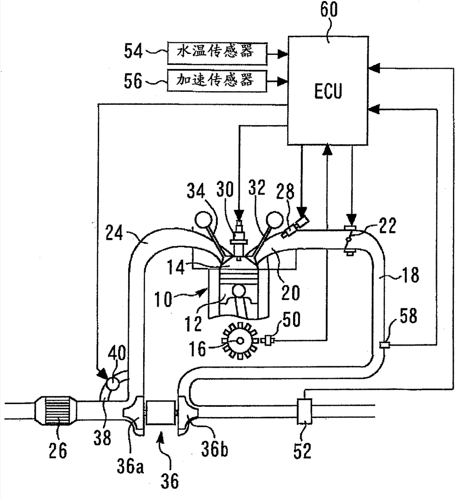
[0034] Below, refer to Figure 1 to Figure 12 Embodiment 1 of the present invention will be described. figure 1 It is an overall configuration diagram for explaining the system configuration of Embodiment 1 of the present invention. The system of the present embodiment includes an engine 10 as a multi-cylinder internal combustion engine. in, figure 1 Only one cylinder among the plurality of cylinders mounted in the engine 10 is exemplified. In each cylinder of the engine 10, a combustion chamber 14 is formed by a piston 12, and the piston 12 is connected to a crankshaft 16 of the engine.

[0035] Further, the engine 10 includes an intake passage 18 for taking intake air into each cylinder, and an intake port 20 opening into the combustion chamber 14 (in-cylinder) of each cylinder is provided on the downstream side of the intake passage 18 . In addition, an electronically controlled throttle valve 22 that adjusts the amount of intak...


PUM


Abstract

The purpose of the present invention is to stably control air-fuel ratio in parallel with WGV control when one is performed. An engine (10) is provided with a supercharger (36), a waste gate valve (WGV; 40), and the like. An ECU (60) calculates a wall-surface-attached fuel amount (FMW) indicating the amount of fuel attached to the wall surface of an intake port (20) on the basis of a plurality of parameters including the opening degree of the WGV (40) or an index corresponding to the opening degree. The ECU (60) then reflects the calculated wall-surface-attached fuel amount (FMW) in a fuel injection amount (ETAUout). In this way, the state of the amount of blow-back of exhaust gas that changes depending on the WGV opening degree can be reflected in the wall-surface-attached fuel amount, i.e., the fuel injection amount, even when WGV control is performed, so that disturbance or the like in the air-fuel ratio due to a change in the blow-back amount can be suppressed.

Description

technical field [0001] The present invention relates to a control device for an internal combustion engine including a supercharger and a wastegate valve (WGV), which can be applied as, for example, an automobile engine. Background technique [0002] As a prior art, there is known a control device for an internal combustion engine configured to control a fuel injection amount using a dynamic behavior model of fuel as disclosed in Patent Document 1 (Japanese Patent Application Laid-Open No. 10-159632 ), for example. In the prior art, the ratio of the fuel adhering to the wall surface of the intake port or the like, that is, the wall surface fuel adhering rate, and the ratio of the adhered fuel remaining on the wall surface, that is, the wall surface fuel remaining rate, are variably set as the dynamic behavior model. parameters, which are used to correct the fuel injection quantity. [0003] Among them, as documents related to the present invention, in addition to the above-...

Claims


Application Information

Patent Timeline
Patent Type & Authority Applications(China)
IPC IPC(8): F02D41/04F02D23/00F02D41/02F02D41/06F02D45/00
CPCF02B37/18F02D23/02F02D41/047F02D2200/0406Y02T10/144F02D41/0007F02D2250/34Y02T10/12
Inventor 井上政广
Owner TOYOTA JIDOSHA KK
Why Eureka
Try Eureka