Rope-guiding hydraulic winch

A hydraulic winch and rope pulling technology, applied in the direction of hoisting device, spring mechanism, etc., can solve the problems of easy rope, many layers, etc., achieve orderly arrangement, improve the effect of rope arrangement, and avoid the effect of disordered arrangement

Active Publication Date: 2015-09-23
ZHEJIANG NOWVOW MECHANICAL & ELECTRICAL
View PDF8 Cites 17 Cited by
  • Summary
  • Abstract
  • Description
  • Claims
  • Application Information

AI Technical Summary

Problems solved by technology

[0003] The existing hydraulic winch row rope is very easy to mess up when the rope is long and there are many layers, especially when the rope is not loaded

Method used


Image

  • Rope-guiding hydraulic winch
  • Rope-guiding hydraulic winch
  • Rope-guiding hydraulic winch

Examples


Embodiment Construction

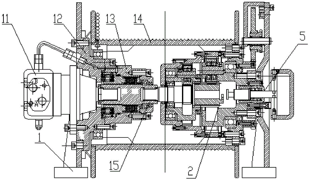
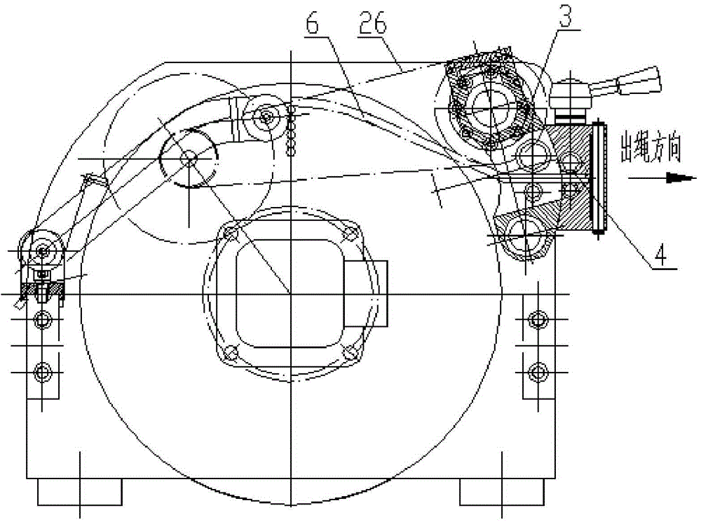
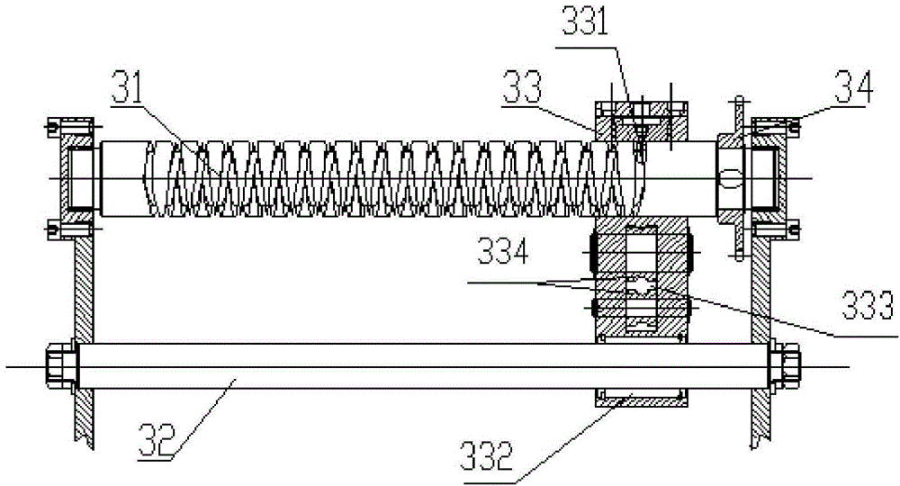
[0026] Such as Figure 1 to Figure 9 As shown, a rope hydraulic winch includes a bracket 1 and a drum 14 mounted on the bracket 1. A hydraulic motor 11 and a brake 13 are provided on the first side of the inner cavity of the drum 14 in the axial direction. A planetary gear reduction device 2 is provided on the second side of the axial direction. The output shaft of the hydraulic motor 11 is connected with the input shaft 211 of the planetary gear reduction device 2. The planetary gear reduction device 2 drives the drum 14 to rotate, and the rope hydraulic winch There is also an automatic rope arrangement 3. The hydraulic motor 11 is mounted on the motor connecting plate 12, and the motor connecting plate 12 is provided with an axial flange which extends into the inside of the drum 14 between the axial flange and the inner ring of the drum. A bearing is provided, and the output end of the hydraulic motor 11 is installed in the inner cavity of the motor connecting plate 12. The...


PUM


Abstract

The invention discloses a rope-guiding hydraulic winch. The rope-guiding hydraulic winch comprises an automatic rope aligning device. The automatic rope aligning device comprises a reciprocating shaft, a guide shaft and a rope aligning base. The reciprocating shaft and the guide shaft are arranged on the circumferential outer side of a winding drum and are parallel to the axial direction of the winding drum. A bidirectional spiral groove is formed in the reciprocating shaft. A meshed tooth is arranged on the rope aligning base and meshed with the bidirectional spiral groove. A rope aligning hole for a steel wire rope to penetrate through is formed in the rope aligning base. A guide hole is formed in the rope aligning base and is in sliding fit with the guide shaft. While the reciprocating shaft synchronously rotates along with the winding drum, the rope aligning base moves in the axial direction of the reciprocating shaft and drives the steel wire rope on the rope aligning base to move together. A rope pressing device for tightly pressing the steel wire rope is arranged on the rope aligning base. By means of the rope-guiding hydraulic winch, the steel wire rope is tidily and orderly arranged on the winding drum, disorderly arranging of the steel wire rope and pressing and abrasion, which are caused by disorderly rope arranging, of the steel wire rope are avoided, the workloads generated when the rope is manually wound can be greatly reduced, and the service life of the steel wire rope can be prolonged.

Description

Technical field [0001] The invention relates to a hydraulic winch. Background technique [0002] The hydraulic winch is mainly composed of hydraulic motors, brakes, drums, drum supports, reduction gearboxes and other accessories. Most of the mounting flanges of hydraulic motors on the market are designed at the front, only extending the output shaft. The brake only needs to consider the size of the motor shaft and flange mounting size to be matched and connected with the motor. The reducer is a multi-stage planetary gear reducer, and the output torque is the planet carrier of the last stage. The planet carrier uses the shaft output to finally connect with the winch drum to output torque, and rotate the winch to pull the heavy object. [0003] The existing hydraulic winch lay-up rope is easy to be messy when the rope is long and there are many layers, especially when the lay-up is not loaded. Summary of the invention [0004] The technical problem to be solved by the present inve...

Claims


Application Information

Patent Timeline
Patent Type & Authority Applications(China)
IPC IPC(8): B66D1/74B66D1/36B66D1/22B66D1/08
CPCB66D1/08B66D1/22B66D1/36B66D1/7463
Inventor 陈恩涯胡骁张昱张杰汤良道
Owner ZHEJIANG NOWVOW MECHANICAL & ELECTRICAL
Why Eureka
Try Eureka