Terminal switching method and base station
A terminal switching and base station technology, applied in the field of communication, can solve the problems of switching service interruption, data packet loss, etc., and achieve the effect of avoiding transmission packet loss and good user perception
- Summary
- Abstract
- Description
- Claims
- Application Information
AI Technical Summary
Problems solved by technology
Method used
Image
Examples
Embodiment 1
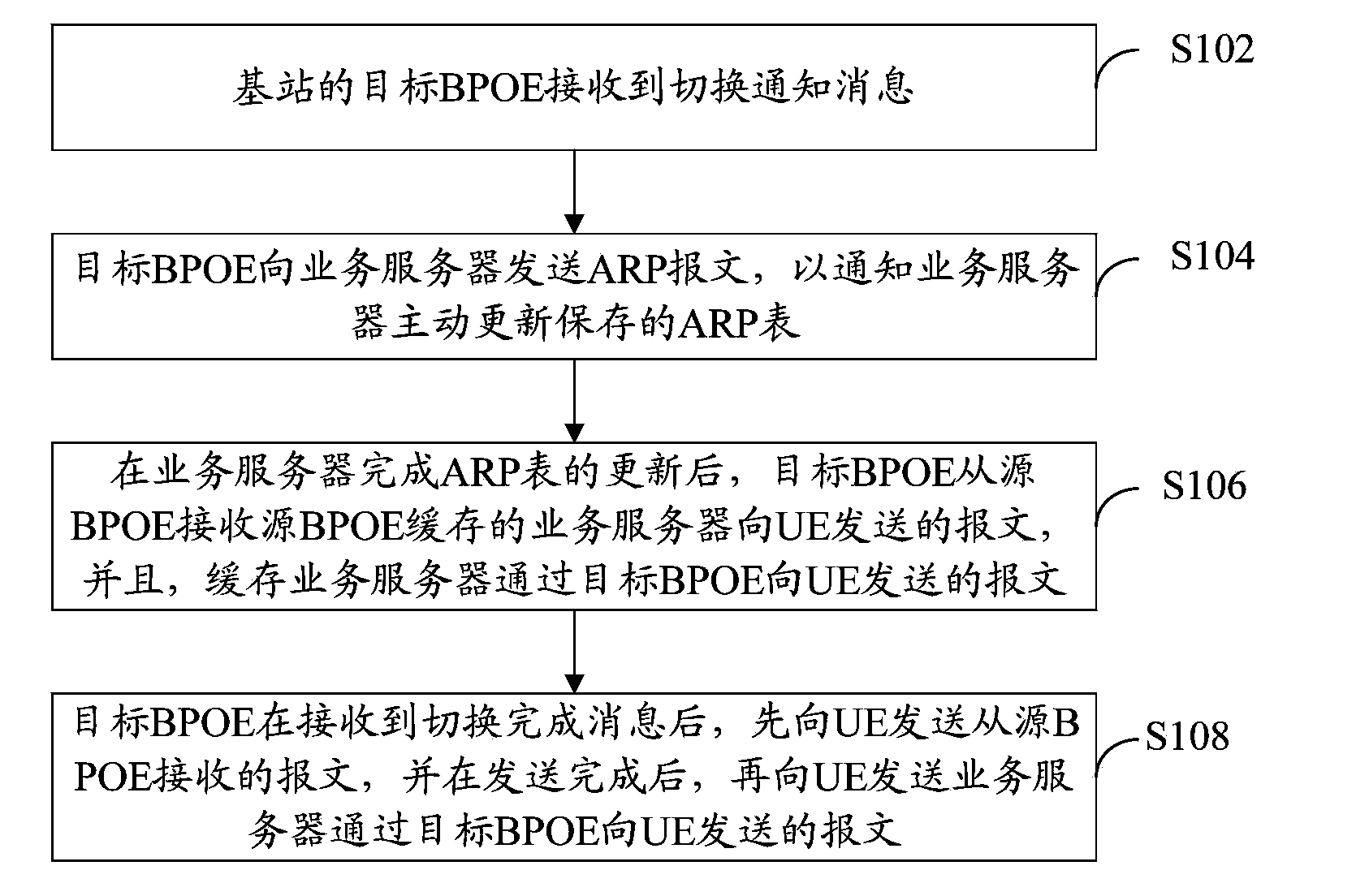
[0035] refer to figure 2 , shows a flow chart of steps of a terminal handover method according to Embodiment 1 of the present invention.
[0036] The terminal handover method of this embodiment is used for terminal handover in a base station without MME mode, including the following steps:
[0037] Step S102: the target BPOE of the base station receives the handover notification message.
[0038] Wherein, the handover notification message is used to notify the UE to handover from the source BPOE to the target BPOE of the base station.
[0039] In this embodiment, the handover notification message is sent by the upper layer of the base station, wherein the upper layer of the base station adopts the conventional meaning in this field, including PDCP (Packet Data Convergence Protocol, packet data convergence protocol) layer and RLC (Radio Link Control, wireless link control) layer.
[0040] Step S104: the target BPOE sends an ARP message to the service server to notify the se...
Embodiment 2
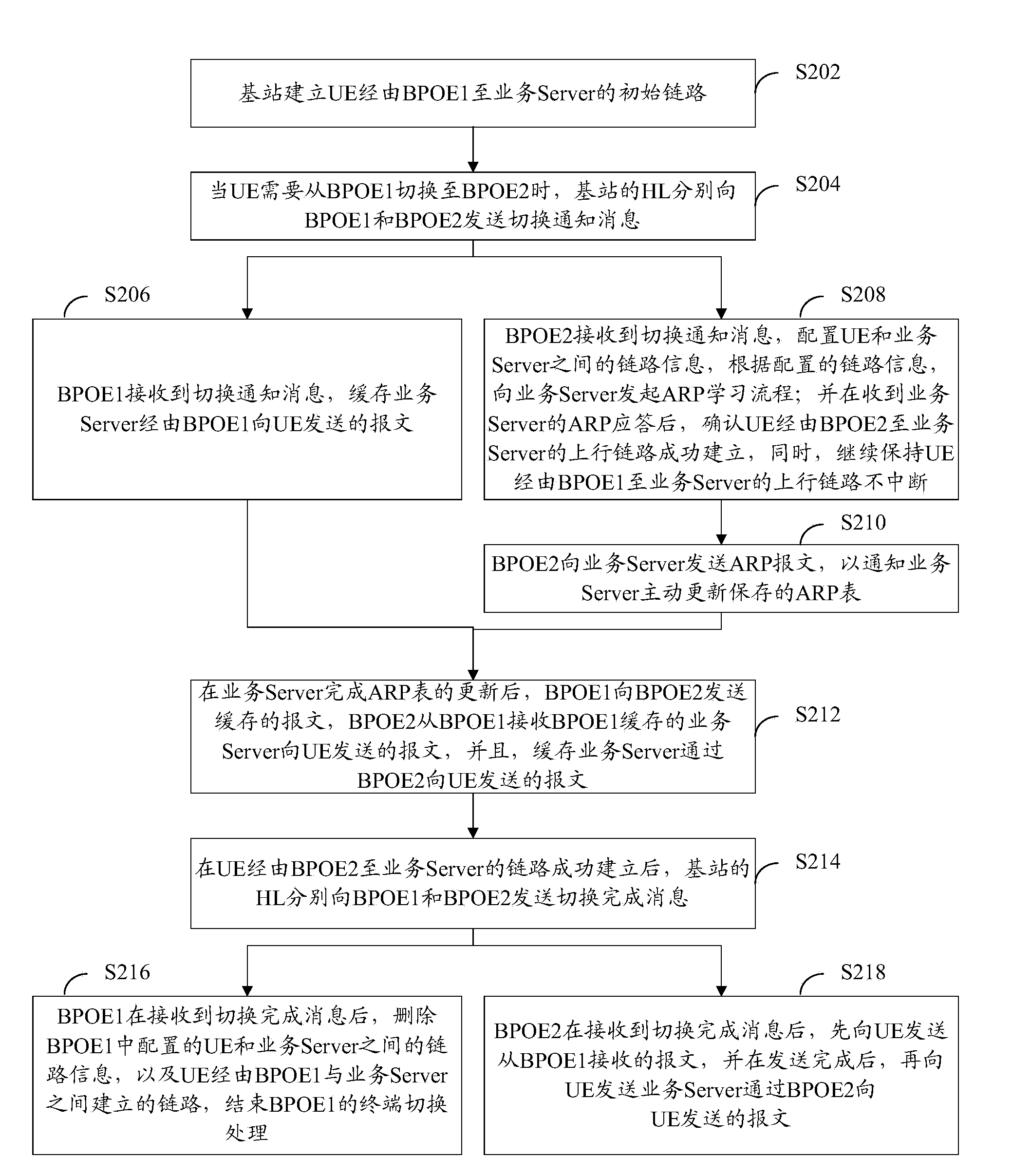
[0050] refer to image 3 , shows a flow chart of steps of a terminal handover method according to Embodiment 2 of the present invention.
[0051] In this embodiment, the source BPOE of the base station is set to be BPOE1, and the target BPOE is set to BPOE2. Taking UE switching from BPOE1 to BPOE2 as an example, the terminal switching solution of the present invention is described.
[0052] The terminal handover method of this embodiment is used for terminal handover in a base station without MME mode, including the following steps:
[0053] Step S202: the base station establishes an initial link from the UE to the service server via the BPOE1.
[0054] The eNodeB provides a transparent transmission channel for the UE and the service server. In the initial stage, if the UE is attached to the cell covered by BPOE1, the eNodeB sends the information of the UE and the service server (including the IP address of the UE, the IP address of the service server, gateway, code, etc.) o...
Embodiment 3
[0075] refer to Figure 4 , which shows a processing flow chart of terminal handover at the source side according to Embodiment 3 of the present invention.
[0076] This embodiment describes the terminal handover scheme of the present invention from the source BPOE side. The source-side terminal handover processing flow in this embodiment is used for the source-side processing of the terminal handover in the base station in the non-MME mode. The flow includes:
[0077] Step S302: The source-side BPOE board DD (Device Driver, device driver layer in the eNodeB) receives the initialization link establishment message sent by the HL.
[0078] Step S304: The DD of the source-side BPOE configures UE and service server information, including UE's IP address, Server's IP address, gateway, and mask.
[0079] Step S306: The DD of the source BPOE sends an ARP request to the service server to initiate an ARP learning process.
[0080] Step S308: The DD of the source BPOE receives the ARP...
PUM
 Abstract
Description
Claims
Application Information
 - R&D
- Intellectual Property
- Life Sciences
- Materials
- Tech Scout
- Unparalleled Data Quality
- Higher Quality Content
- 60% Fewer Hallucinations
Browse by: Latest US Patents, China's latest patents, Technical Efficacy Thesaurus, Application Domain, Technology Topic, Popular Technical Reports.
© 2025 PatSnap. All rights reserved.Legal|Privacy policy|Modern Slavery Act Transparency Statement|Sitemap|About US| Contact US: help@patsnap.com


