Photoelectric scattering detector for beverage

A detector and light detection technology, applied in the biological field, can solve problems such as high production cost, unfavorable instrument popularization and promotion, and large drift tube volume, and achieve the goal of improving baseline stability, facilitating popularization and promotion, and reducing noise level Effect

Inactive Publication Date: 2015-01-21
SHANGHAI HAOJIE BIOTECH
View PDF8 Cites 3 Cited by
  • Summary
  • Abstract
  • Description
  • Claims
  • Application Information

AI Technical Summary

Problems solved by technology

[0004] However, during the working process of the beverage photoelectric scattering detector, the mobile phase may produce some corrosive gases during the atomization of the mobile phase by the nebulizer, and these corrosive gases will be released immediately. It flows into the drift tube, and the current material for making the drift tube is basically steel pipe, which does not have strong corrosion resistance. Therefore, the corrosive gas flowing out of the atomizer during use will corrode the drift tube, thereby reducing the photoelectric scattering of the drink. Detector lifetime
Someone proposed to change the material of the drift tube into a corrosion-resistant steel pipe to solve this problem. Although the corrosion-resistant steel pipe can resist the corrosion of corrosive gases, the material of the corrosion-resistant steel pipe is metal, and the production cost is relatively high. Increase the production cost of the beverage photoelectric scattering detector, which is not conducive to the popularization and promotion of the instrument
[0005] In addition, the minimum diameter of the drift tube currently used in the photoelectric scattering detector for beverages is 14mm (millimeter), and the maximum thickness of the tube wall is 1mm (millimeter). Large, and the drift tube is connected in multiple helical shapes when it is connected between the nebulizer and the optical detection cell, which leads to a low concentration of the mobile phase with a low flow rate in the drift tube, and the instrument cannot detect the components in the mobile phase

Method used


Image

  • Photoelectric scattering detector for beverage
  • Photoelectric scattering detector for beverage
  • Photoelectric scattering detector for beverage

Examples


Embodiment Construction

[0024] In order to make the object, technical solution and advantages of the present invention clearer, various embodiments of the present invention will be described in detail below in conjunction with the accompanying drawings. However, those of ordinary skill in the art can understand that, in each implementation manner of the present invention, many technical details are provided for readers to better understand the present application. However, even without these technical details and various changes and modifications based on the following implementation modes, the technical solution claimed in each claim of the present application can be realized.

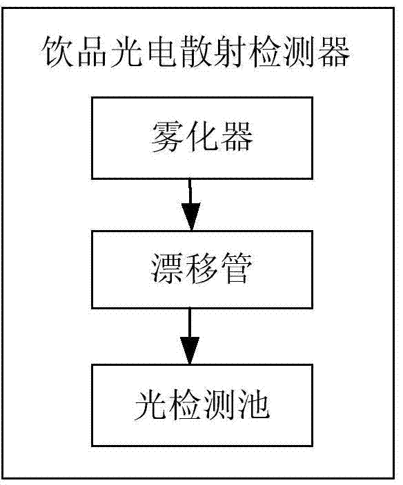
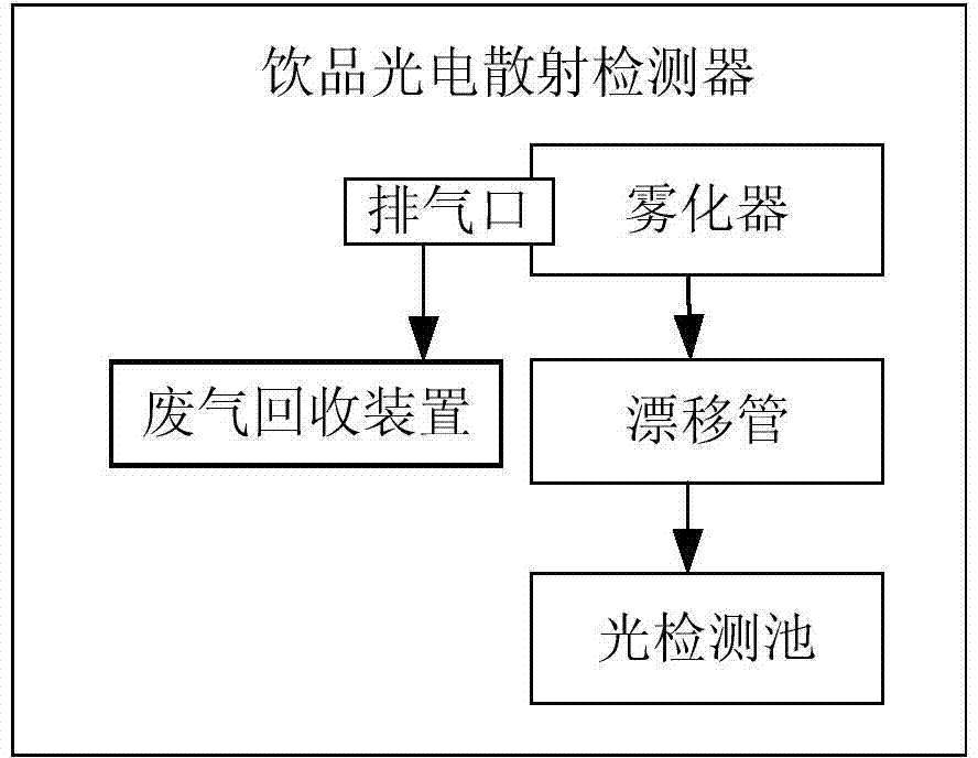
[0025] Such as figure 1 As shown, the beverage photoelectric scattering detector in the prior art includes an atomizer 101, a drift tube 102 and a light detection cell 103, and the atomizer 101, the drift tube 102 and the light detection cell 103 are connected in sequence. During the working process of the beverage photoele...


PUM

PropertyMeasurementUnit
diameteraaaaaaaaaa
thicknessaaaaaaaaaa

Abstract

The invention relates to the technical field of biology, and discloses a photoelectric scattering detector for a beverage. The photoelectric scattering detector for the beverage comprises an atomizer, a drift tube and an optical detection tank, wherein the atomizer, the drift tube and the optical detection tank are connected successively; and the drift tube is made of ceramics. The photoelectric scattering detector for the beverage takes use of the ceramic to make the drift tube of the photoelectric scattering detector for the beverage, so that the drift tube has the characteristic of corrosion resistance. A manufacturing cost of the photoelectric scattering detector for the beverage is low, thereby facilitating popularization and promotion of the photoelectric scattering detector for the beverage. The photoelectric scattering detector for the beverage is used for detecting components in a mobile phase.

Description

technical field [0001] The invention relates to the field of biotechnology, and discloses a beverage photoelectric scattering detector. Background technique [0002] The beverage detector is used to detect the substances that should not be contained in the beverage according to the production standards of the enterprise or the production standard of the industry. Researchers can also use this instrument to conduct scientific experiments. The commonly used beverage detector on the market is the beverage photoelectric scattering detector. The structure of the beverage photoelectric scattering detector includes an atomizer, a drift tube and a light detection cell, and the atomizer, drift tube and light detection cell are connected in sequence. [0003] The working principle of the instrument is as follows: the detected mobile phase is mixed with the carrier gas flow such as nitrogen or air through the nebulizer to form a mist liquid; the nebulizer is followed by a drift tube, a...

Claims


Application Information

Patent Timeline
Patent Type & Authority Applications(China)
IPC IPC(8): G01N21/49
Inventor 李昭何杰邹垚何萍鲁湛
Owner SHANGHAI HAOJIE BIOTECH
Why Eureka
Try Eureka