
Method, device and equipment for determining beamforming weight

A beamforming and weighting technology, which is applied in the field of determining beamforming weights, can solve the problems of unpredictable UE channel status, unbalanced number of antennas, failure to well realize SU-MIMO and MU-MIMO joint transmission scheme, etc. question

Active Publication Date: 2019-08-20
ZTE CORP
View PDF4 Cites 2 Cited by
  • Summary
  • Abstract
  • Description
  • Claims
  • Application Information

AI Technical Summary

Problems solved by technology

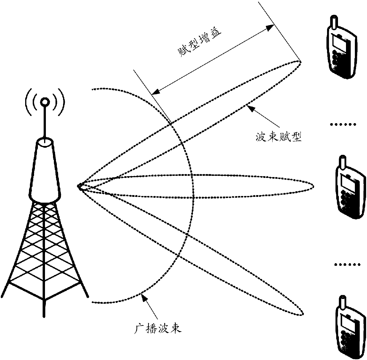
[0004] Most of the existing user equipment (User Equipment, UE) antennas are configured as: uplink single-antenna transmission and downlink two-antenna reception, that is, the number of antennas configured for uplink and downlink is unbalanced, resulting in the inability to realize the combination of SU-MIMO and MU-MIMO well Transmission scheme; Specifically, if the closed-loop precoding technology is used, since the base station cannot predict the channel state of the UE in advance, generally only the broadcast weighted pilot signal can be used, and then the UE selects a corresponding codebook based on the pilot to feed back to the base station, and the base station based on This codebook is used for the weighting of data services, but this leads to the inability to share the same time-frequency resources between multiple UEs, that is, the space division strategy cannot be used; if the open-loop precoding scheme is used, the base station can only obtain the main set of UEs The channel state of the antenna (antenna port used for uplink transmission), so that each UE can only perform single-stream shaping, so SU-MIMO cannot be realized; therefore, the existing scheme cannot realize the combination of SU-MIMO and MU-MIMO transmission

Method used


Image

  • Method, device and equipment for determining beamforming weight
  • Method, device and equipment for determining beamforming weight
  • Method, device and equipment for determining beamforming weight

Examples


Embodiment Construction

[0051] The following will clearly and completely describe the technical solutions in the embodiments of the present invention with reference to the drawings in the embodiments of the present invention.

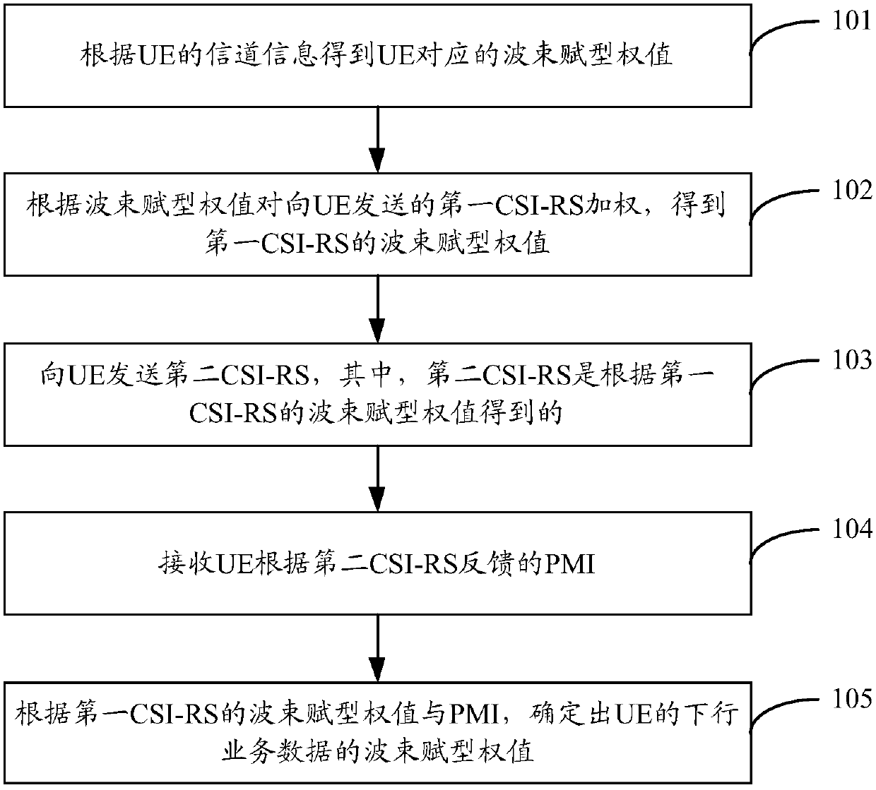
[0052] figure 1 The flow chart of Embodiment 1 of the method for determining beamforming weights in the present invention, as shown in figure 1 As shown, the method for determining the beamforming weight provided by the embodiment of the present invention can be applied to the device for determining the beamforming weight (hereinafter referred to as the device), and the method may include:

[0053] Step 101. Obtain beamforming weights corresponding to the UE according to channel information of the UE.

[0054] The device uses the principle of uplink and downlink reciprocity between the UE and the uplink measurement signal to obtain the beamforming weight corresponding to the UE. If there are multiple UEs, a set of beamforming weights is constructed, and each UE corresponds to...


PUM


Abstract

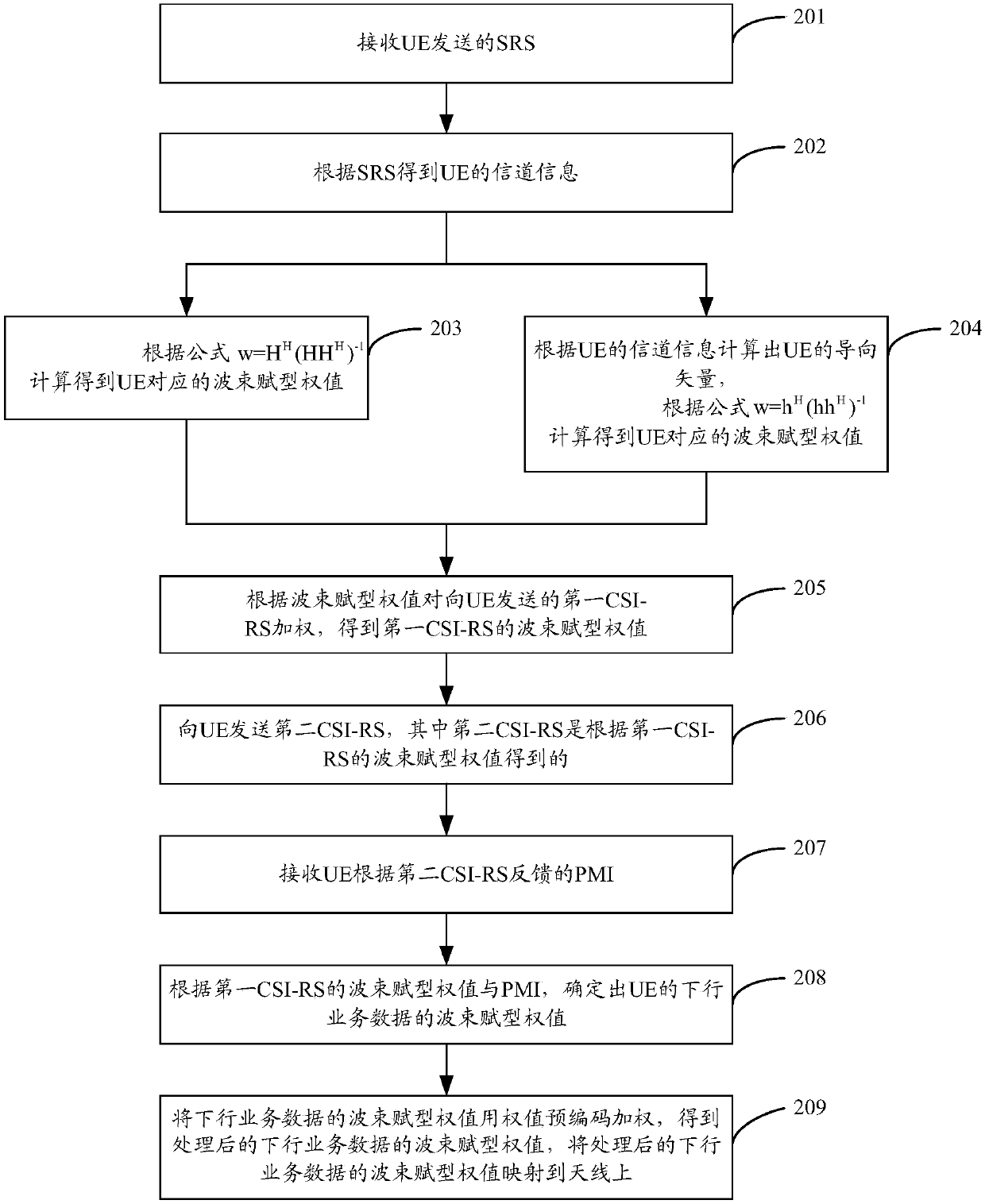
The invention discloses a method for determining a beamforming weight. The method comprises the following steps: obtaining a beamforming weight corresponding to UE according to channel information ofthe UE; weighting first CSI-RS sent to the UE according to the beamforming weight to obtain a beamforming weight of the first CSI-RS; sending a second CSI-RS to the UE, wherein the second CSI-RS is obtained according to the beamforming weight of the first CSI-RS; receiving a precoding matrix index PMI fed back by the UE according to the second CSI-RS; according to the beamforming weight of the first CSI-RS and the PMI, determining the beamforming weight of the downlink service data of the UE. The invention also discloses a device and equipment for determining the beamforming weight.

Description

technical field [0001] The present invention relates to the technical field of wireless communication, in particular to a method, device and equipment for determining beamforming weights. Background technique [0002] Multi-antenna technology is a major breakthrough in the field of wireless communication, also known as Multiple-Input Multiple-Output (MIMO) technology, which can improve the capacity and spectrum utilization of the communication system without increasing the bandwidth. Improving the reliability of the channel and reducing the bit error rate without increasing the transmission power of the whole system are key technologies that must be adopted in the new generation of mobile communication systems. [0003] MIMO technology uses multiple antennas to transmit and receive at both the transmitting end and the receiving end. MIMO technology is mainly divided into diversity technology and multiplexing technology: diversity technology uses multiple copies of the signal...

Claims


Application Information

Patent Timeline
IPC IPC(8): H04B7/0456H04B7/06H04B7/08
CPCH04B7/0456H04B7/0617H04B7/0626H04B7/0634H04B7/0639H04B7/086H04B7/08H04B7/06Y02D30/70
Inventor 艾星星
Owner ZTE CORP
Learn More