Supercharge Your Innovation With Domain-Expert AI Agents!

An internal self-cleaning centrifugal fan

A centrifugal fan, self-cleaning technology, used in mechanical equipment, machines/engines, liquid fuel engines, etc., can solve the problem of difficult to clean pollutants

Active Publication Date: 2021-06-04
太仓欧昌五金机械有限公司
View PDF8 Cites 0 Cited by
  • Summary
  • Abstract
  • Description
  • Claims
  • Application Information

AI Technical Summary

Problems solved by technology

[0005] The purpose of the present invention is to solve the problem that the above-mentioned pollutants are accumulated in a large amount inside and it is difficult to clean, and to provide an internal self-cleaning centrifugal fan that automatically sweeps and discharges dust and pollutants while enhancing the air intake efficiency

Method used


Image

  • An internal self-cleaning centrifugal fan
  • An internal self-cleaning centrifugal fan
  • An internal self-cleaning centrifugal fan

Examples


Embodiment 1

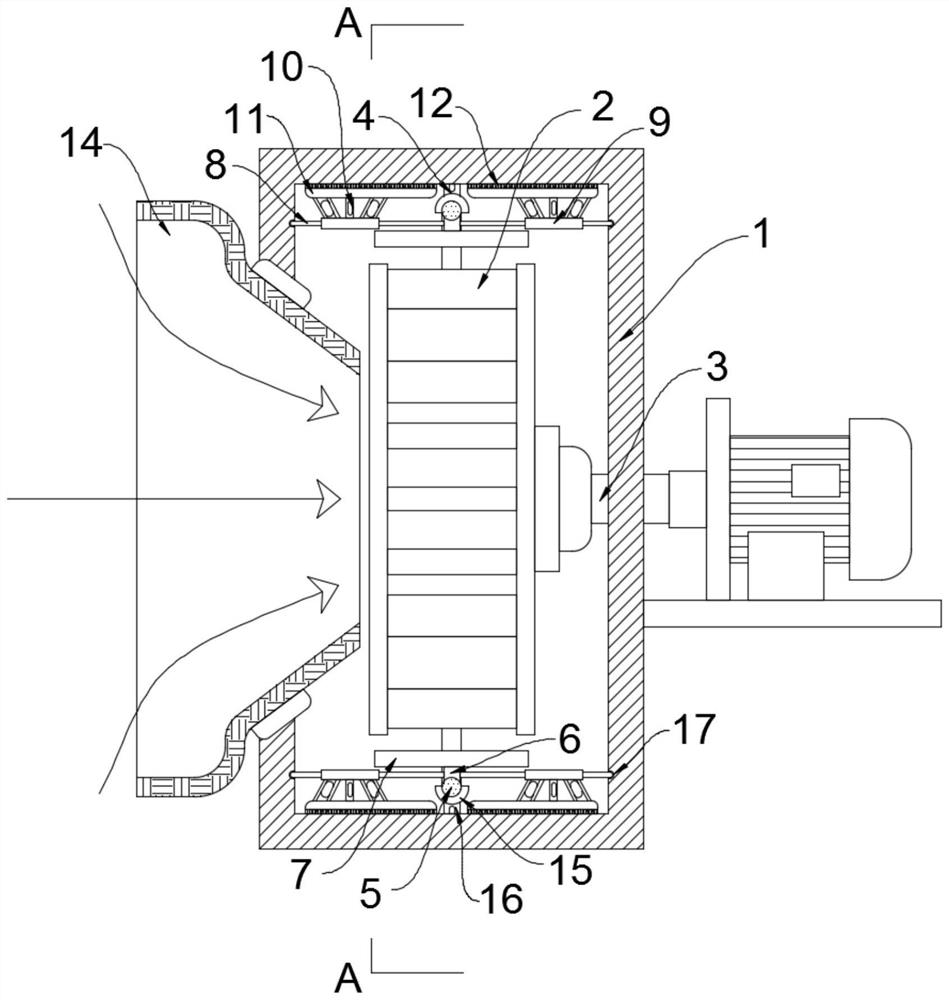
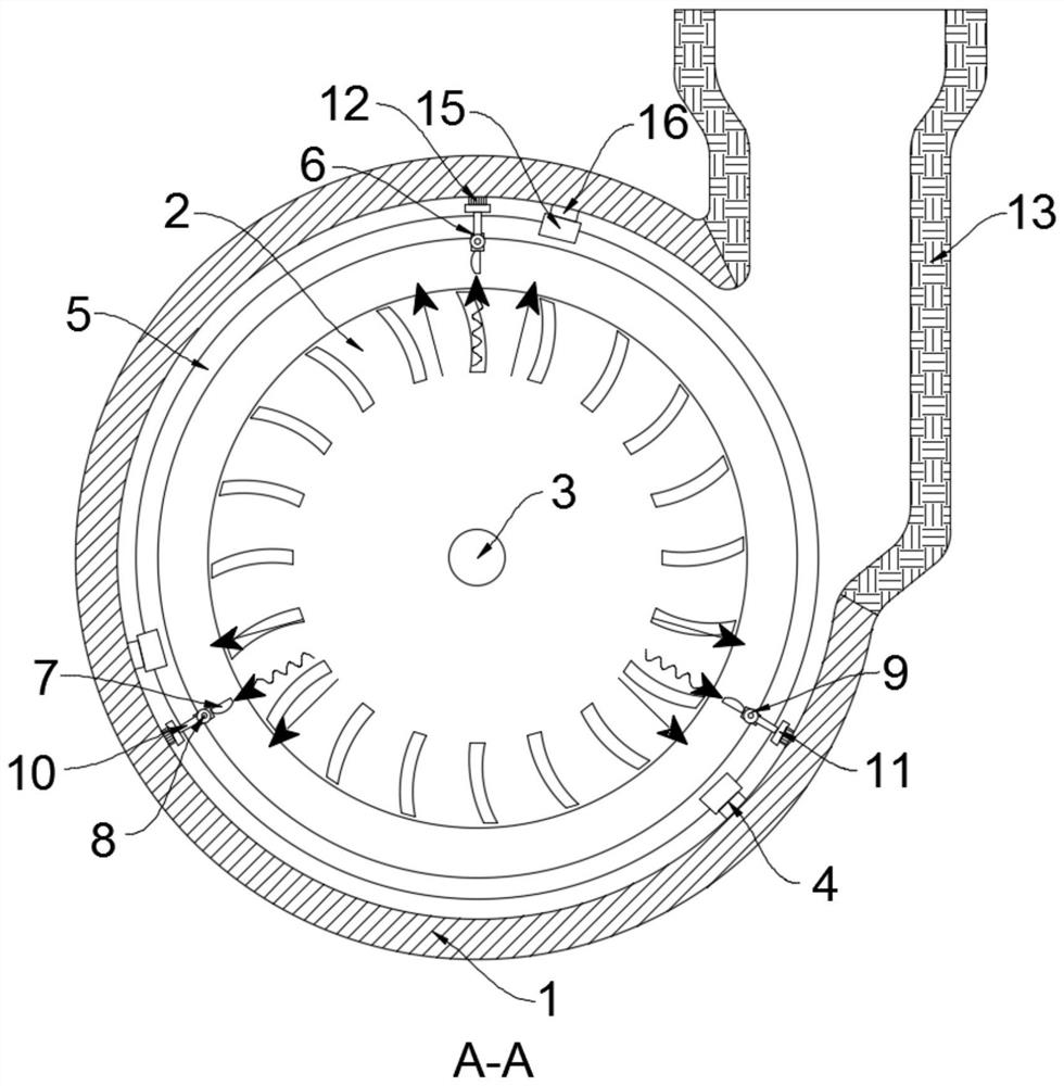
[0021] Such as Figure 1-2 As shown, an internal self-cleaning centrifugal fan includes a housing 1, the housing 1 is provided with an impeller 2, the outer wall of the housing 1 is provided with a driving mechanism, and the driving mechanism drives the impeller 2 to rotate through the rotating shaft 3, and the inner side of the housing 1 The position of the wall corresponding to the impeller 2 is fixedly connected with a plurality of support members 4, and the same slide ring 5 is slidably connected to the plurality of support members 4. Specifically, the support member 4 includes an arc-shaped support ring 15, and the support ring 15 and the slide ring 5 is slidingly connected, the lower end of the support ring 15 is fixedly connected to the inner side wall of the housing 1 through the support block 16, and the support ring 15 is slidably connected to the sliding ring 5 through a plurality of balls.

[0022] In this embodiment, the upper end of the sliding ring 5 is fixedly ...

Embodiment 2

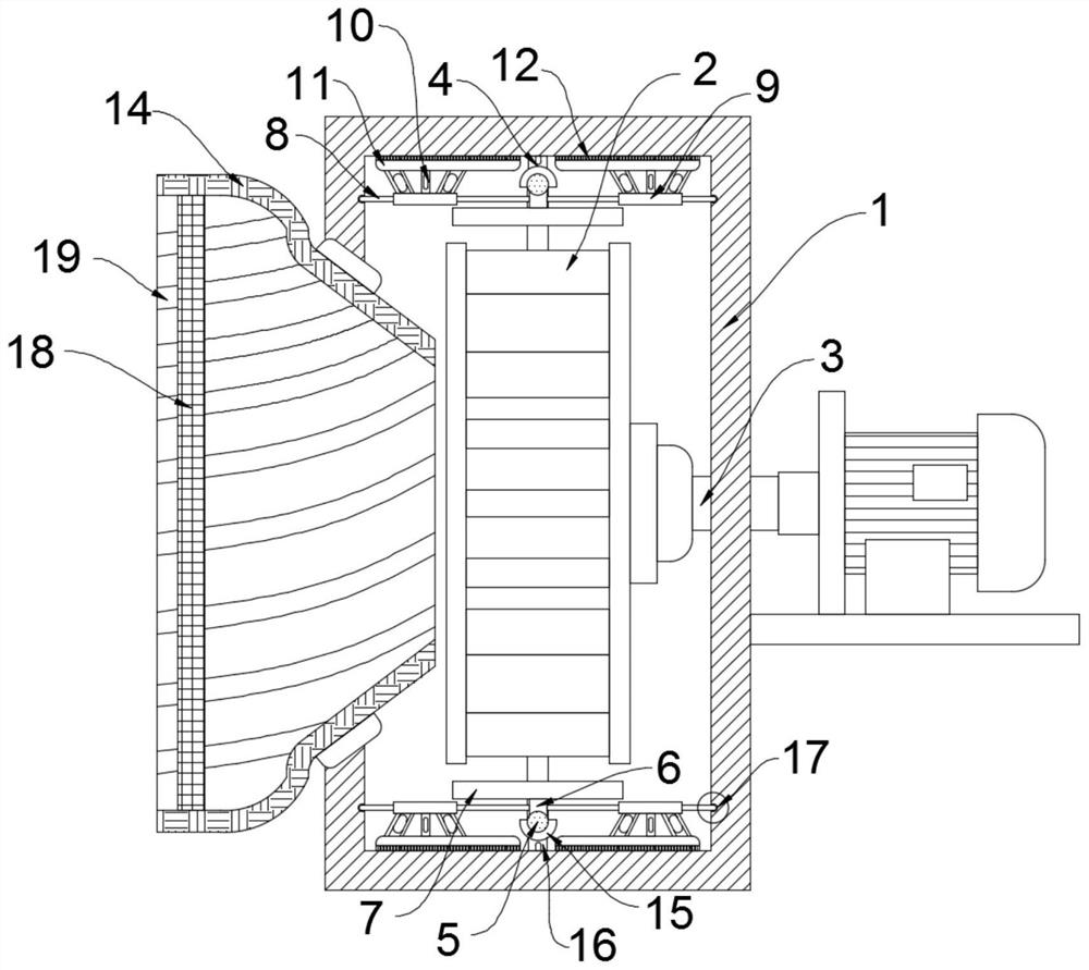
[0028] Such as Figure 3-4 As shown, the difference between this embodiment and Embodiment 1 is: the setting of the threaded bar 19, when the ventilator is working, a large amount of outside air is sucked from the air inlet tube 14, wherein a part of the air comes from the left and right sides of the air inlet tube 14 side rather than the direction facing the air inlet tube 14, this part of the air will be inclined in a certain direction after being sucked into the air inlet tube 14, and will continue to flow in the air inlet tube 14 until it hits the side wall of the air inlet tube 14 Finally, a part of the air is brought in by the horizontal wind of the mainstream, while the other part is reflected after the impact and continues to move in the air inlet tube 14 with an oblique attitude, which leads to the existence of multiple directions in the air inlet tube 14. The airflows collide or push each other to form a turbulent flow area, which causes the air intake efficiency of ...


PUM


Abstract

The invention belongs to ventilation and related fields, and in particular relates to an internal self-cleaning high-efficiency centrifugal fan, which includes a casing, an impeller is arranged inside the casing, a driving mechanism is arranged on the outer wall of the casing, the driving mechanism drives the impeller to rotate through a rotating shaft, and the outer casing The inner wall is fixedly connected with a plurality of supports, and the same sliding ring is slidably connected to the plurality of supports, the upper end of the sliding ring is fixedly connected with a connecting block, the upper end of the connecting block is fixedly connected with a fin plate, and both ends of the connecting block are fixedly connected with a sliding ring. The rod, the sliding rod is slidingly connected with the inner wall of the housing, the sliding rod is fixedly sleeved with a fixed sleeve, the fixed sleeve, the side of the fixed sleeve close to the inner wall of the housing is fixedly connected with a brush plate through a plurality of fixed blocks, and the bristles and the housing The inner walls of the body are in contact with each other, the upper end of the housing is provided with an air outlet tube, and the side wall of the housing is provided with an air inlet tube corresponding to the axis of the impeller. The present invention can automatically clean and blow out the dust inside the shell during the working period of the ventilator by setting the sliding ring.

Description

technical field [0001] The invention belongs to the related field of centrifugal fans, in particular to an internal self-cleaning centrifugal fan. Background technique [0002] Centrifugal fan is a machine that relies on input mechanical energy to increase gas pressure and discharge gas. It is widely used in almost every industry, such as ventilation, dust removal and ventilation of factories, mines, tunnels, cooling towers, vehicles, ships and buildings. Cooling, ventilation and drafting of boilers and industrial furnaces, etc. [0003] Due to its wide application and different working environments, when the outside air quality is poor, the general centrifugal fan will only induce air through the impeller and then push the air out through the outlet due to its fixed structure. The air duct has no selectivity for air absorption, so that a large amount of dust, impurities, pollutants and even corrosion in the absorbed air adhere to the pipes and inside the ventilator, result...

Claims


Application Information

Patent Timeline
Patent Type & Authority Patents(China)
IPC IPC(8): F04D17/16F04D29/70F04D29/42F04D29/44F04D29/66
CPCF04D17/16F04D29/4213F04D29/4226F04D29/441F04D29/667F04D29/703
Inventor 雷帅
Owner 太仓欧昌五金机械有限公司
Features
  • R&D
  • Intellectual Property
  • Life Sciences
  • Materials
  • Tech Scout
  • Unparalleled Data Quality
  • Higher Quality Content
  • 60% Fewer Hallucinations
Learn More