
An adjustable lighting lamp for indoor lighting

A technology for indoor lighting and lighting lamps, applied in lighting devices, lighting devices, fixed lighting devices, etc., can solve the problems of single function, inconvenient cleaning, and invariable lighting range, and achieve the effect of convenient use and simple operation

Active Publication Date: 2022-04-26
苏州中亿丰光电有限公司
View PDF0 Cites 0 Cited by
  • Summary
  • Abstract
  • Description
  • Claims
  • Application Information

AI Technical Summary

Problems solved by technology

[0004] The purpose of the present invention is to solve the shortcomings of the existing lighting lamps that the range of illumination is mostly invariable, not suitable for people to use in different time periods, and has a single function, and is inconvenient to clean, and proposes an adjustable indoor lighting. flashlight

Method used


Image

  • An adjustable lighting lamp for indoor lighting
  • An adjustable lighting lamp for indoor lighting
  • An adjustable lighting lamp for indoor lighting

Examples


Embodiment 1

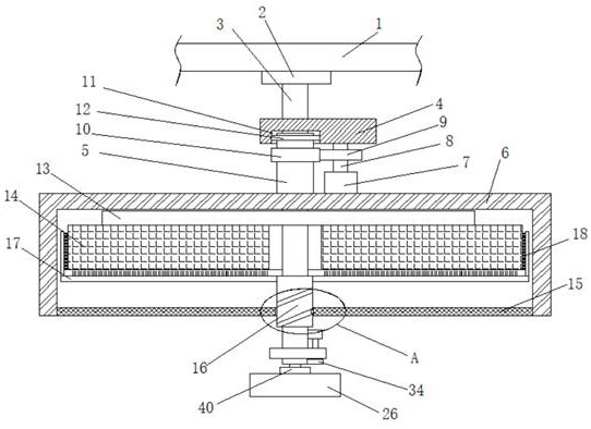
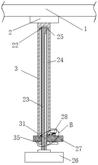
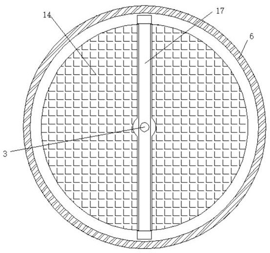
[0029] refer to Figure 1-5 , an adjustable lighting lamp for indoor lighting, comprising a ceiling 1, a lamp holder 2 fixedly installed on the bottom of the The bottom of the plate 4 is rotatably connected with a rotating plate 5, the rotating plate 5 is threadedly connected with the fixed rod 3, and the bottom of the rotating plate 5 is rotatably connected with a cover plate 6, and the top of the cover plate 6 is fixedly installed with a first motor 7, the first motor The first rotating rod 8 is fixedly installed on the output shaft of 7, and the first rotating rod 8 is rotationally connected with the moving plate 4, and the first rotating rod 8 is connected with the rotating plate 5 in transmission, and a positioning seat 13 is fixedly installed on the fixed rod 3, The bottom of the positioning seat 13 is fixedly equipped with an illuminating lamp 14, the bottom of the cover plate 6 is fixedly equipped with a transparent decorative plate 15, and the outer rotation sleeve of...

Embodiment 2

[0040] refer to Figure 1-5 , an adjustable lighting lamp for indoor lighting, comprising a suspended ceiling 1, a lamp holder 2 welded to the bottom of the suspended ceiling 1, a fixed rod 3 welded to the bottom of the lamp holder 2, a movable plate 4 slidingly connected to the fixed rod 3, and a movable plate 4 The bottom of the rotating plate 5 is rotatably connected with a rotating plate 5, and the rotating plate 5 is threadedly connected with the fixed rod 3, and the bottom of the rotating plate 5 is rotatably connected with a cover plate 6, and the top of the cover plate 6 is fixed with a first motor 7 by bolts, and the first motor 7 The first rotating rod 8 is welded on the output shaft of the motor, the first rotating rod 8 is rotationally connected with the moving plate 4, and the first rotating rod 8 is connected with the rotating plate 5 in transmission, the fixed rod 3 is welded with a positioning seat 13, and the positioning seat 13 The bottom of the cover plate 6...


PUM


Abstract

The invention belongs to the technical field of lighting lamps, in particular to an adjustable lighting lamp for indoor lighting. The illumination range of the lighting lamp is mostly invariable, and it is not suitable for people to use in different time periods, and the function is single and inconvenient to clean. , the following scheme is proposed, which includes a suspended ceiling, the bottom of the suspended ceiling is fixedly installed with a lamp holder, the bottom of the lamp holder is fixedly installed with a fixed rod, the fixed rod is slidably connected to a moving plate, and the bottom of the moving plate is rotatably connected to a rotating plate, The rotating plate is threadedly connected with the fixed rod, and the bottom of the rotating plate is rotatably connected with a cover plate, the top of the cover plate is fixedly mounted with a first motor, the output shaft of the first motor is fixedly mounted with a first rotating rod, and the first rotation The rod is rotatably connected with the moving plate. The invention is simple in operation and convenient in use, can adjust the illumination range of the illuminating lamp, can also clean the illuminating lamp, and can also adjust the height of the decorative lamp, which is convenient for people to use.

Description

technical field [0001] The invention relates to the technical field of lighting lamps, in particular to an adjustable lighting lamp for indoor lighting. Background technique [0002] Indoor lighting can be used in the living room, bathroom or bedroom of the family, and can also be used in shops, etc. With the development of the times, lighting fixtures, as daily consumables, have become an indispensable tool for people's home lighting. [0003] Most of the existing lighting lamps have a fixed range of illumination, are not suitable for people to use in different time periods, and have a single function and are inconvenient to clean. Therefore, we propose an adjustable lighting lamp for indoor lighting. Contents of the invention [0004] The purpose of the present invention is to solve the shortcomings of the existing lighting lamps that the range of illumination is mostly invariable, not suitable for people to use in different time periods, and has a single function, and i...

Claims


Application Information

Patent Timeline
Patent Type & Authority Patents(China)
IPC IPC(8): F21S8/06F21V14/00F21V33/00F21V17/12F21V14/02
CPCF21S8/063F21V14/006F21V33/0004F21V17/12F21V14/02
Inventor 张金新王华辉
Owner 苏州中亿丰光电有限公司
Learn More