Flange plate detection device

A technology of detection device and limit device, which is applied to measurement devices, optical devices, instruments, etc., can solve the problems such as the inability of flanges to fit each other, the damage of flanges, and the uneven surface of flanges. Achieve the effect of preventing incomplete fit and avoiding errors

Inactive Publication Date: 2020-08-18
田振龙
View PDF22 Cites 0 Cited by
  • Summary
  • Abstract
  • Description
  • Claims
  • Application Information

AI Technical Summary

Problems solved by technology

[0007] The problem solved by the present invention is that the roundness and surface smoothness of the flange are not detected when the flange is detected, and the flange is not round enough to cause damage after installation for a certain period of time. If the surface of the flange is not flat enough, there will be no way for the two corresponding flanges to fit together during installation.

Method used


Image

  • Flange plate detection device
  • Flange plate detection device
  • Flange plate detection device

Examples


Embodiment 1

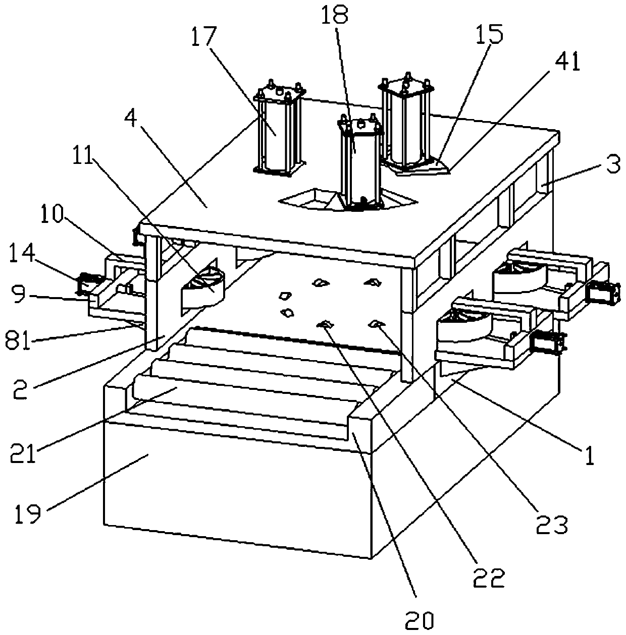
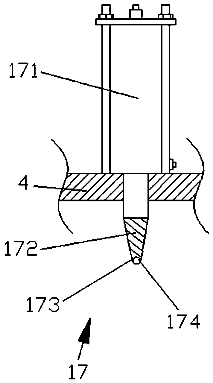
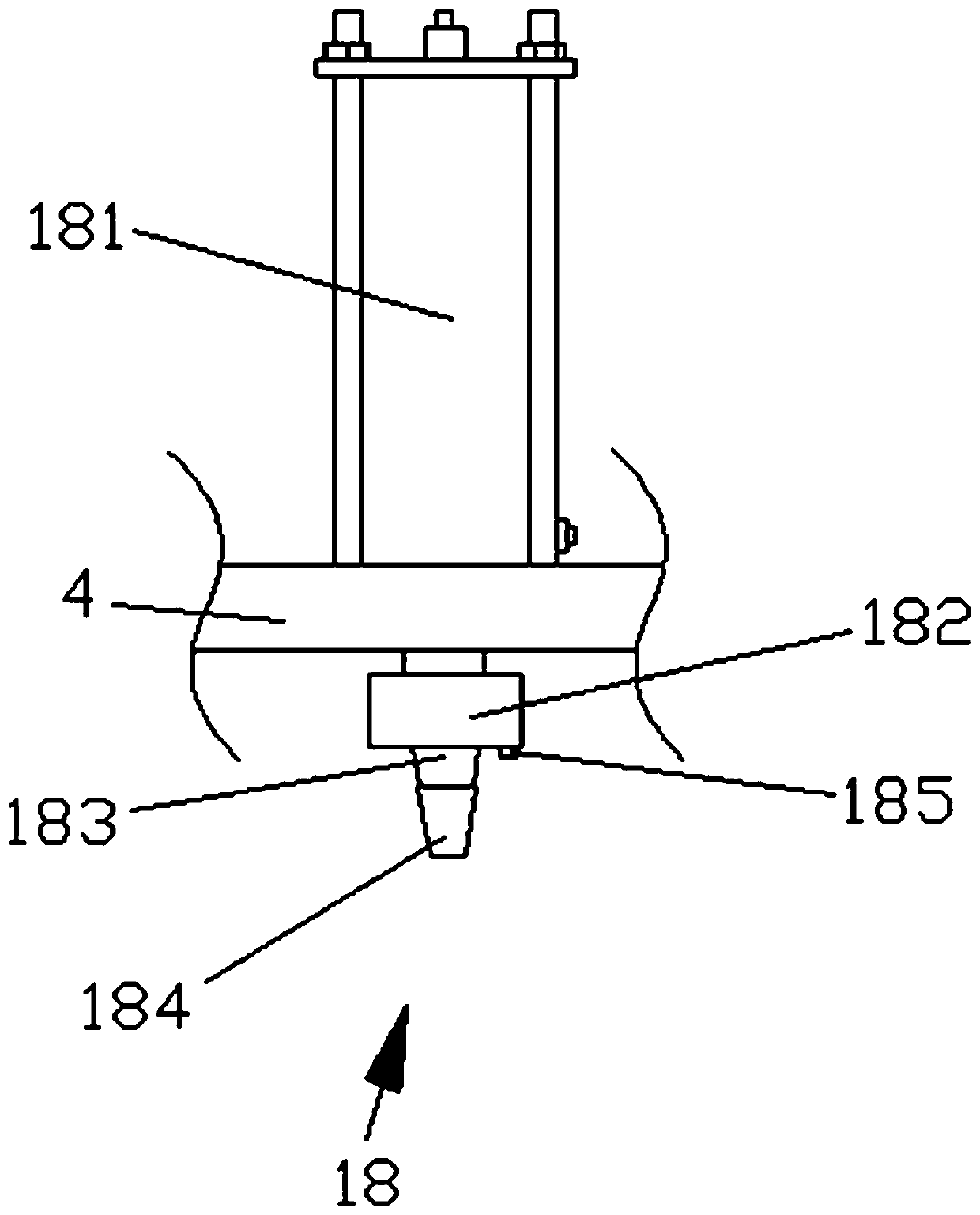
[0032] see figure 1 , figure 2 , image 3 , Figure 6 and Figure 7 Shown: a flange detection device, including a bottom plate 1, fixedly connected with two symmetrical fixed plates 2 on the upper side of the bottom plate 1, a top plate 4 is fixed on the fixed plate 2 through a group of connecting columns 3, and the A group of positioning devices 5 are installed on the top board 4 , and two limiting devices 6 are installed on each fixing board 2 .

[0033]The purpose of the present invention can be achieved through the following technical solutions: the fixed plate 2 is provided with two through holes 7, the through holes 7 are square and arranged symmetrically in pairs, the limiting device 6 is arranged inside the through holes 7, and the limiting device 6 includes a first support plate 8, the first support plate 8 is vertically inserted on the fixed plate 2, and the first support plate 8 is fixedly connected to the fixed plate 2 with bolts, and the first support plate 8...

Embodiment 2

[0043] Such as Figure 4 , Figure 5 , Figure 6 , Figure 7 As shown: including the bottom plate 1, two symmetrically arranged fixed plates 2 are fixedly connected on the upper side of the bottom plate 1, and the top plate 4 is fixed on the fixed plate 2 through a group of connecting columns 3, and a set of positioning devices are installed on the top plate 4 5. Two limit devices 6 are installed on each fixed plate 2. There are two through holes 7 on the fixed plate 2. The through holes 7 are square and arranged symmetrically. The limit devices 6 are set in the through holes 7. Inside, the limiting device 6 includes a first support plate 8, the first support plate 8 is vertically plugged on the fixed plate 2, and the first support plate 8 is fixedly connected to the fixed plate 2 using bolts, and the first support plate 8 is connected to the fixed plate 2. One end of the second support plate 9 is fixed, the first support plate 8 and the second support plate 9 are verticall...


PUM


Abstract

The invention discloses a flange plate detection device. the device comprises a bottom plate. Two symmetrically-arranged fixing plates are fixedly connected to the upper side of the bottom plate. A top plate is fixed on the fixed plate through a group of connecting columns. A group of positioning devices are mounted on the top plate. Two limiting devices are mounted on each fixing plate. A first detection device is fixed on the top plate. A plurality of arc-shaped mounting holes are formed in the top plate. A second detection device is mounted in each mounting hole. The second detection deviceis slidably connected with the mounting hole. Errors caused by displacement of the to-be-detected flange plate during detection are avoided, and the position of the second detection device can be adjusted according to the accurate data position of the hole in the flange plate, so that the flange plate detection device can adapt to detection work of most flange plates with different opening positions, and the problem that two flange plates cannot be completely attached during actual use is effectively prevented.

Description

technical field [0001] The invention relates to the field of connector detection, in particular to a flange detection device. Background technique [0002] Flanges are referred to as flanges for short, and they are just a general term. They usually refer to opening several holes for fixing on the periphery of a disc-like metal body for connecting other things. This thing is widely used in machinery, so it looks strange, as long as it looks like a flange, its name comes from the English flange. [0003] Flange is also called flange or flange. The part that connects the pipe to the pipe, connected to the pipe end. There are holes in the flange, and the bolts tightly connect the two flanges. The flanges are sealed with gaskets. Flange is a disc-shaped part, the most common in pipeline engineering, flanges are used in pairs. In pipeline manufacturing, Flanges are mainly used for the link of pipelines. At the ends that need to connect the two pipelines, install a flange. de...

Claims


Application Information

Patent Timeline
Patent Type & Authority Applications(China)
IPC IPC(8): G01B11/30
CPCG01B11/30G01B11/306
Inventor 田振龙
Owner 田振龙
Why Eureka
Try Eureka