Ball cutter compensation method and device applied to stone mill curved surface machining, terminal and computer readable storage medium

A technology of curved surface processing and compensation method, applied in computer control, general control system, instrument, etc., can solve the problems of expensive ball cutter, irreversible positioning deviation, discontinuous surface to be processed, etc.

Active Publication Date: 2020-08-18
江西正皓瑞森精密智能制造股份有限公司
View PDF9 Cites 2 Cited by
  • Summary
  • Abstract
  • Description
  • Claims
  • Application Information

AI Technical Summary

Problems solved by technology

Ball cutters wear as machining progresses, negatively impacting surface machining accuracy
[0003] At present, the research on ball cutter compensation in graphite curved surface processing is not enough. Usually, the method of changing the cutter is used to keep the cutter in an ideal surface state and ensure the machining accuracy.
Tool replacement is time-consuming and labor-intensive, and recalibration and adjustment are required after the replacement, and there is an irreversible positioning deviation in the position of the blade before and after the tool change, which makes the surface to be processed discontinuous and the machining accuracy is difficult to guarantee
At the same time, the ball cutter is expensive, and the frequent replacement of the cutter makes the processing cost high

Method used


Image

  • Ball cutter compensation method and device applied to stone mill curved surface machining, terminal and computer readable storage medium
  • Ball cutter compensation method and device applied to stone mill curved surface machining, terminal and computer readable storage medium
  • Ball cutter compensation method and device applied to stone mill curved surface machining, terminal and computer readable storage medium

Examples


Embodiment 1

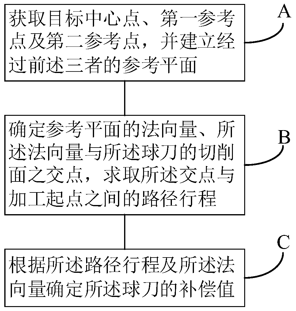
[0054] Please refer to Figure 1~2 , the present embodiment provides a ball cutter compensation method applied to stone grinding curved surface processing, the method includes the following steps:

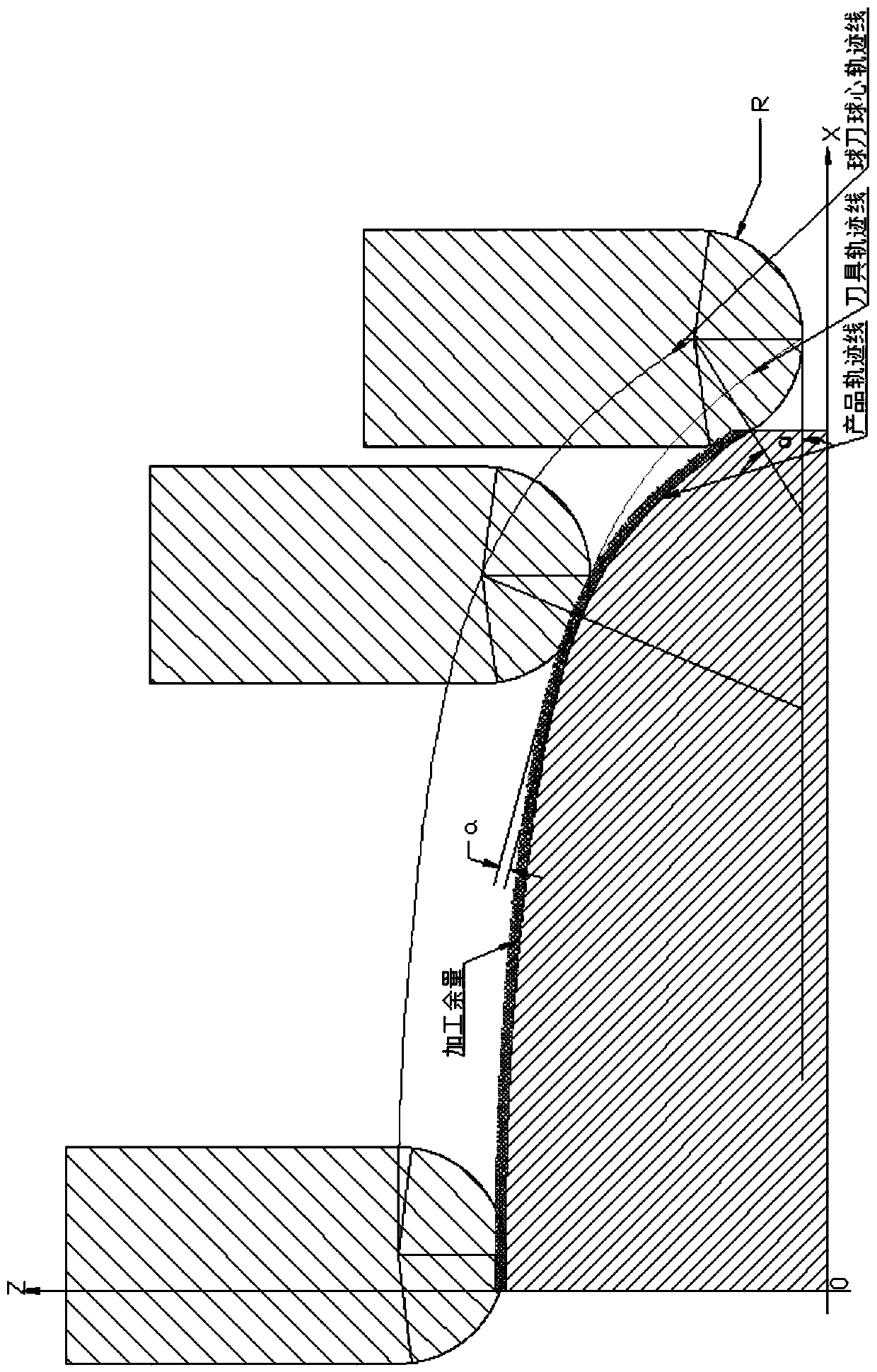
[0055] Step A: Obtain the target center point, the first reference point and the second reference point, and establish a reference plane passing through the above three. Wherein, the target center point is the center position of the ball cutter when it passes through the processing point to be compensated, and the first reference point and the second reference point are the centers of the ball cutter closest to the target center point on the adjacent processing path position, the adjacent processing path remains adjacent to the processing path where the target center point is located. The so-called center position of the ball knife refers to the position of the ball center of the spherical blade of the ball knife.

[0056] When machining the curved surface of the graphite materia...

Embodiment 2

[0076] see Figure 5 , this embodiment provides a ball cutter compensation device applied to stone grinding curved surface processing, the device includes:

[0077] The plane establishment module 110 is used to obtain the target center point, the first reference point and the second reference point, and establish a reference plane passing through the above three, the target center point is the center position of the ball cutter when it passes through the processing point to be compensated, The first reference point and the second reference point are the center positions of the ball cutter closest to the target center point on the adjacent processing path, and the adjacent processing path remains adjacent to the processing path where the target center point is located ;

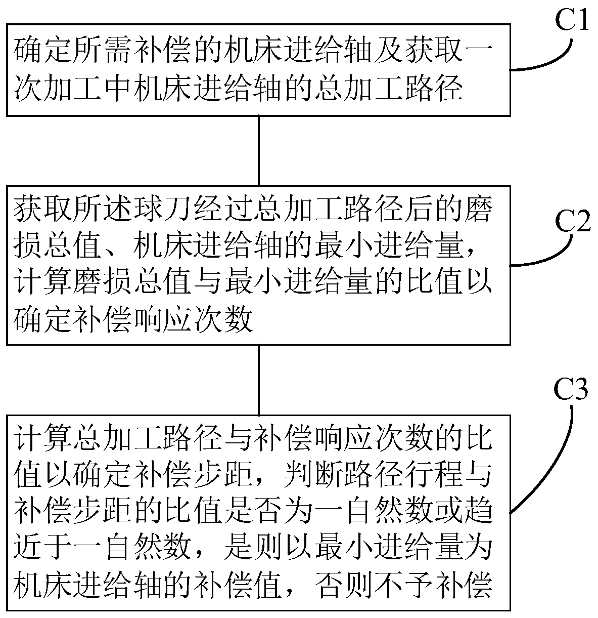
[0078] Compensation fixed-point module 120, used to determine the normal vector of the reference plane, the intersection point of the normal vector and the cutting surface of the ball cutter, and calculate th...

Embodiment 3

[0090] see Figure 8 , the present embodiment provides a terminal 200, the terminal 200 includes a memory 210 and a processor 220, the memory 210 is used to store a computer program, and the processor 220 executes the computer program to enable the terminal 200 to implement the above-mentioned application in stone grinding curved surface processing ball cutter compensation method.

[0091] Wherein, the terminal 200 includes terminal devices (such as computers, servers, etc.) that do not have mobile communication capabilities, and also includes mobile terminals (such as smart phones, tablet computers, vehicle-mounted computers, smart wearable devices, etc.).

[0092] The memory 210 may include an area for storing programs and an area for storing data. Wherein, the storage program area can store the operating system, at least one application program required by the function (such as sound playback function, image playback function, etc.); the storage data area can store data cr...


PUM


Abstract

The invention discloses a ball cutter compensation method and device applied to stone mill curved surface machining, a terminal and a computer readable storage medium. The ball cutter compensation method comprises the following steps: obtaining a target center point, a first reference point and a second reference point, and building a reference plane passing through the former three points, wherein the target center point is the center position when the ball cutter passes through the to-be-compensated machining point, the first reference point and the second reference point are the center positions, closest to the target center point, of the ball cutter on the adjacent machining paths, and the machining paths where the adjacent machining paths are located are kept adjacent to the machiningpath where the target center point is located; determining a normal vector of the reference plane and an intersection point of the normal vector and the cutting surface of the ball cutter, and solving a path stroke between the intersection point and a machining starting point; and determining a compensation value of the ball cutter according to the path travel and the normal vector. According tothe ball cutter compensation method and device, the terminal and the computer readable storage medium, synchronous compensation on the cutter is achieved, cutter abrasion errors are approximately eliminated, the curved surface machining precision is guaranteed, the service life of the cutter is prolonged, and the cutter cost is reduced.

Description

technical field [0001] The invention belongs to the technical field of numerical control machining, and specifically relates to a ball cutter compensation method, device, terminal and computer-readable storage medium applied to machining curved surfaces of stone mills. Background technique [0002] The curved surface processing of graphite materials generally requires the use of ball cutters. During the machining process, the ball cutter makes point contact with the surface of the graphite material, and the material is cut and removed by the high-speed rotation of the blade. As machining progresses, the ball cutters wear, negatively affecting surface machining accuracy. [0003] At present, the research on ball cutter compensation in graphite surface machining is not enough, and the method of changing the cutter is usually used to keep the cutter in an ideal surface state and ensure the machining accuracy. Tool replacement is time-consuming and laborious. After the replace...

Claims


Application Information

Patent Timeline
Patent Type & Authority Applications(China)
IPC IPC(8): G05B19/404
CPCG05B19/404G05B2219/35408
Inventor 李铁骑
Owner 江西正皓瑞森精密智能制造股份有限公司
Why Eureka
Try Eureka