Supercharge Your Innovation With Domain-Expert AI Agents!

CT detector for head CT system

A detector and head technology, which is applied in the field of medical imaging equipment, can solve the problems that it is impossible to obtain images of the patient's head, and achieve the effects of compact detector and CT system structure, shortened distance, and reduced cost

Pending Publication Date: 2020-08-21
NANJING ANKE MEDICAL TECH CO LTD
View PDF17 Cites 2 Cited by
  • Summary
  • Abstract
  • Description
  • Claims
  • Application Information

AI Technical Summary

Problems solved by technology

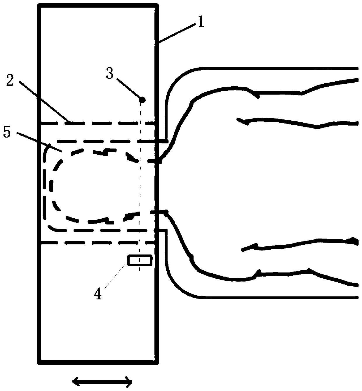
[0005] Two design elements in traditional CT detectors, (1) the use of detector module positioning rails, and (2) the design of the top cover with a fan, so that the X-ray detection array of the detector module is farther away from the top edge of the detector housing distance, impossible figure 1 The compact design of the head CT gantry shown in , results in that if the traditional detector design is used in head CT, the imaging area of ​​the system cannot be close to the patient's shoulder, and the entire head image of the patient cannot be obtained

Method used


Image

  • CT detector for head CT system
  • CT detector for head CT system
  • CT detector for head CT system

Examples


Embodiment Construction

[0025] The present invention will be further explained below in conjunction with the drawings.

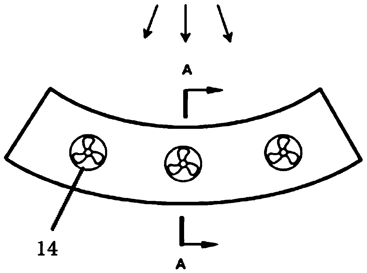
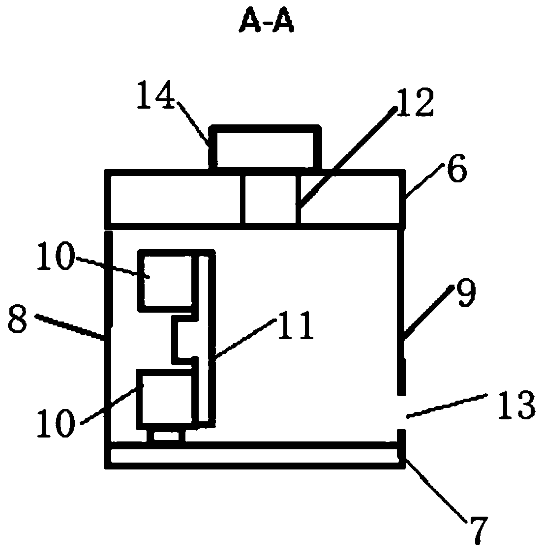
[0026] Such as Figure 3 to 5 As shown, the present invention is a CT detector for a head CT system. The CT detector and the bulb are located on both sides of the gantry hole of the CT system. The CT detector includes a detector housing and a detector module. The housing of the detector is an arc cavity composed of a top cover plate, a bottom plate, an inner arc plate and an outer arc plate. The inner arc plate is provided with an incident window, and a plurality of detector modules are arranged in the arc cavity along the arc direction. .

[0027] Such as Figure 5 As shown, the top cover plate is provided with an air inlet; the bottom plate is provided with an air outlet, and a fan is provided inside the air outlet. The fan can be attached to the bottom plate with fasteners. The detector module includes a detector unit and a module holder. The detector unit is arranged close to the...


PUM


Abstract

The invention discloses a CT detector for a head CT system. The CT detector comprises a detector shell and detector modules, the detector shell is an arc-shaped cavity composed of a top cover plate, abottom plate, an inner arc-shaped plate and an outer arc-shaped plate, an incident window is formed in the inner arc-shaped plate, the multiple detector modules are arranged in the arc-shaped cavityin the arc direction, and an air inlet is formed in the top cover plate; an air outlet is formed in the bottom plate, and a fan is arranged at the air outlet; the detector module comprises a detectorunit and a module support, the detector unit is close to the top cover plate and fixed to the upper portion of the module support, and the lower portion of the module support is fixed to the bottom plate on the side, close to the inner arc-shaped plate, of the air outlet. According to the invention, an X-ray detection array of the detector module can be effectively close to the top cover plate ofthe detector shell, so that the requirement of the head CT compact rack design is met.

Description

Technical field [0001] The invention relates to medical imaging equipment, in particular to a CT detector used in a head CT system. Background technique [0002] Head CT scan has become an indispensable imaging method for the diagnosis of head diseases or injuries. It can provide a clear image of the patient's brain anatomy in a short time, significantly improving the detection rate of lesions and the accuracy of diagnosis. Under normal circumstances, head CT scans require the patient to be moved to the radiology department of the hospital to scan using a traditional CT system. For acute and severe patients, moving the patient will bring the risk of deterioration, and the time delay will also affect the timely treatment of the emergency and severe illness. The mobile dedicated head CT system can solve this problem well. The patient can quickly complete the head CT scan on the bed or even on the emergency vehicle without going to the radiology department of the hospital. [0003] ...

Claims


Application Information

Patent Timeline
Patent Type & Authority Applications(China)
IPC IPC(8): A61B6/03A61B6/00G01N23/046
CPCA61B6/035A61B6/4208G01N23/046
Inventor 李文吴小页
Owner NANJING ANKE MEDICAL TECH CO LTD
Features
  • R&D
  • Intellectual Property
  • Life Sciences
  • Materials
  • Tech Scout
  • Unparalleled Data Quality
  • Higher Quality Content
  • 60% Fewer Hallucinations
Learn More