
Industrial environmentally-friendly fan provided with protective base

A technology for protecting bases and fans, applied to mechanical equipment, machines/engines, liquid fuel engines, etc., can solve problems such as difficulty in dismantling fan blades, large limitations of fans, complicated operation process, etc., to save energy and cost, and improve use The effect, the effect of guaranteeing the cleaning effect

Inactive Publication Date: 2020-08-21
浙江当代风机有限公司
View PDF8 Cites 0 Cited by
  • Summary
  • Abstract
  • Description
  • Claims
  • Application Information

AI Technical Summary

Problems solved by technology

The cooling coil, the key component of the high-efficiency cooling fan, is composed of advanced fins and heat exchange tubes, adopts a new technology of tube expansion, advanced design structure of variable fin spacing on the wind-outlet surface, and staggered arrangement of heat exchange tubes to ensure The air flow organization is perfect, the air distribution is even and reasonable, and the efficient heat exchange is realized. It is not easy to frost, and the defrosting is efficient, simple and easy. In the existing industrial fans, the fans are directly placed or installed without effective protection and fixing. There are certain limitations in use, and in industrial fans, the fan blades are prone to dust, and the dust workers on the front only need to remove the protective net to clean it, but the dust on the back of the fan blades must be removed to clean it. , the operation process is complicated, and it is also difficult to disassemble the fan blades, which leads to greater limitations of the fan

Method used


Image

  • Industrial environmentally-friendly fan provided with protective base
  • Industrial environmentally-friendly fan provided with protective base
  • Industrial environmentally-friendly fan provided with protective base

Examples


Embodiment Construction

[0025] In order to make the technical means, creative features, goals and effects achieved by the present invention easy to understand, the present invention will be further described below in conjunction with specific embodiments.

[0026] In the description of the present invention, it should be noted that the terms "upper", "lower", "inner", "outer", "front end", "rear end", "both ends", "one end", "another end" The orientation or positional relationship indicated by etc. is based on the orientation or positional relationship shown in the drawings, and is only for the convenience of describing the present invention and simplifying the description, rather than indicating or implying that the referred device or element must have a specific orientation, use a specific Azimuth configuration and operation, therefore, should not be construed as limiting the invention. In addition, the terms "first" and "second" are used for descriptive purposes only, and should not be understood ...


PUM


Abstract

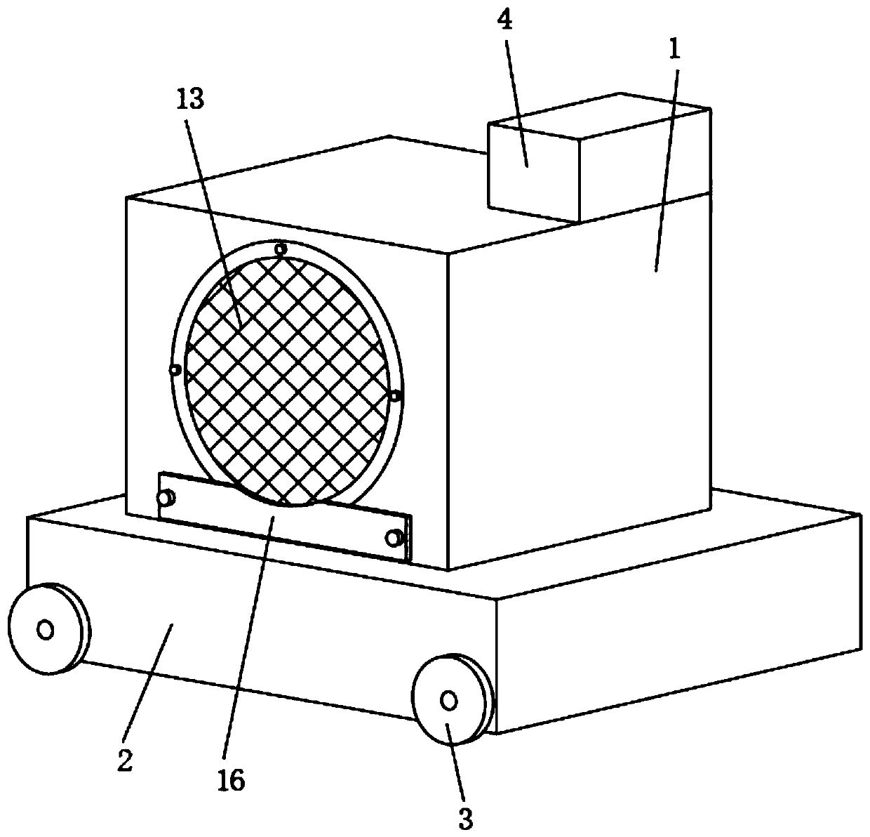
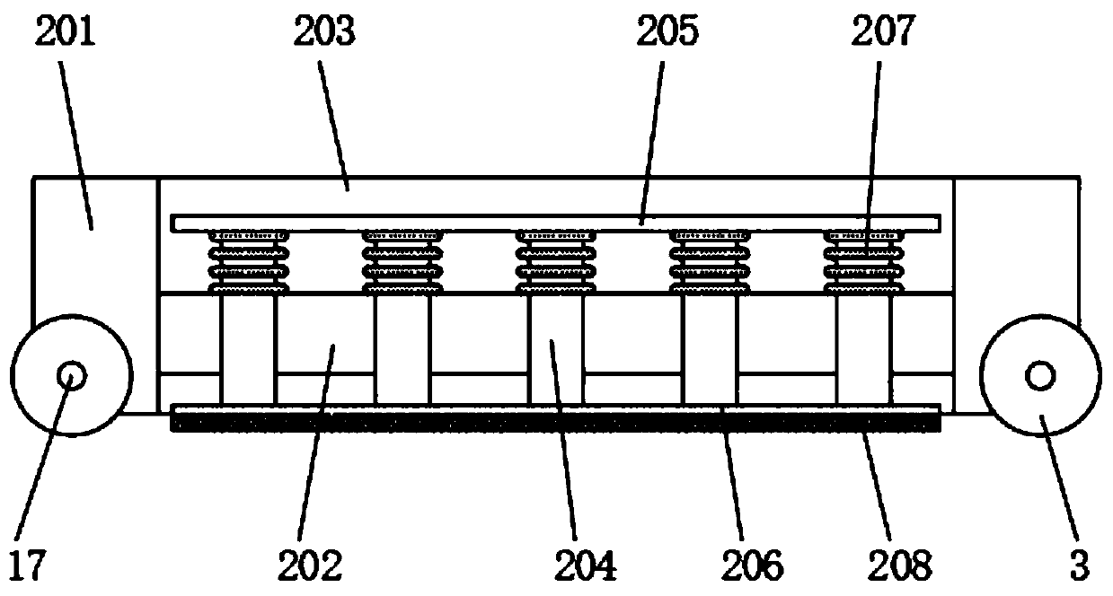
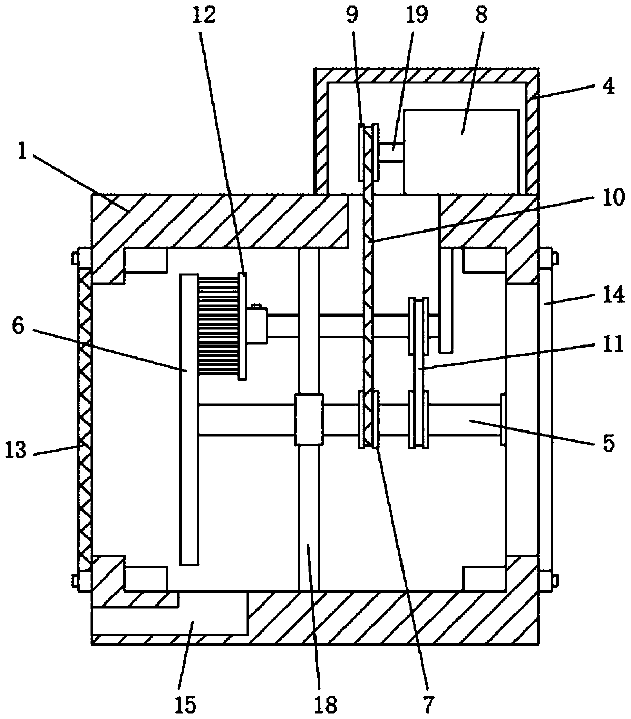
The invention discloses an industrial environmentally-friendly fan provided with a protective base. The industrial environmentally-friendly fan comprises a fan main body; the protective base is arranged at the lower end of the fan main body; a vehicle wheel is arranged on the protective base; a driving box is fixedly mounted at the upper end of the fan main body; and a rotary shaft is arranged inthe fan main body. According to the industrial environmentally-friendly fan, the protective base can effectively mount and fix the fan, also can form protection, is cooperated with a support rod, a buffer spring and other structures for application, and is cooperated with gravity and elastic force application to form linkage during the mounting and dismantling process to improve the using effect;a transmission mechanism and a sweeping mechanism are adopted to sweep the reverse side of a fan blade and also can form linkage to save energy and cost; the sweeping mechanism is detachable, and thestructure at a hairbrush can be detached for changing to ensure the sweeping effect; and a protective structure is arranged to be cooperated with a spring for application and also can assist in a working staff for taking.

Description

technical field [0001] The invention relates to the field of industrial fans, in particular to an industrial environment-friendly fan with a protective base. Background technique [0002] Industrial fans refer to fans that are specially used for ventilation in tunnels, underground garages, high-grade civil buildings, metallurgy, factories and mines, and high-temperature smoke exhaust for fire fighting. It is mainly composed of impeller, casing, inlet collector, deflector, motor and other components. The cooling coil, the key component of the high-efficiency cooling fan, is composed of an advanced design of fins and heat exchange tubes. It adopts a new technology of tube expansion, an advanced design structure with variable fin spacing on the air outlet surface, and the heat exchange tubes are arranged in a staggered manner, ensuring The air flow organization is perfect, the air distribution is even and reasonable, and the efficient heat exchange is realized. It is not easy ...

Claims


Application Information

Patent Timeline
IPC IPC(8): F04D25/08F04D29/70F04D29/66F04D29/00F04D29/60
CPCF04D25/08F04D29/002F04D29/601F04D29/668F04D29/703
Inventor 徐明灿
Owner 浙江当代风机有限公司
Learn More