
Self-adaptive adjustment method for truck brake table and roller brake table for detection

A technology of self-adaptive adjustment and braking platform, which is applied in vehicle testing, measuring device, testing of machine/structural components, etc., can solve the problems that the braking platform cannot be applied to the detection of various types of vehicles, waste resources, etc., and achieve improved synchronization. Rotation, the effect of reducing the use of the motor

Active Publication Date: 2020-08-21
成都成保发展股份有限公司
View PDF15 Cites 0 Cited by
  • Summary
  • Abstract
  • Description
  • Claims
  • Application Information

AI Technical Summary

Problems solved by technology

[0002] According to the implementation regulations of China's Road Traffic Safety Law, trucks and large and medium-sized non-operating passenger vehicles shall be inspected once a year within 10 years, and once every 6 months if they exceed 10 years. Traffic accidents, so it is necessary to regularly detect the braking force of the car. During the inspection, it is necessary to use a brake table to detect the braking performance of the car and the condition of the vehicle wheels. The existing roller detection table has limited rollers, and It is a fixed setting. Because the wheel distribution and the distance between the wheels of different models are different, it is necessary to use the brake table to adapt to different models. It has achieved the purpose of testing multiple models with one brake table. The current brake table cannot be used. The detection of various vehicle models requires multiple devices for detection, wasting resources

Method used


Image

  • Self-adaptive adjustment method for truck brake table and roller brake table for detection
  • Self-adaptive adjustment method for truck brake table and roller brake table for detection
  • Self-adaptive adjustment method for truck brake table and roller brake table for detection

Examples


Embodiment Construction

[0049] In order to make the object, technical solution and advantages of the present invention more clear, the present invention will be further described in detail below in conjunction with the accompanying drawings and embodiments. It should be understood that the specific embodiments described here are only used to explain the present invention, and are not intended to limit the present invention, that is, the described embodiments are only some of the embodiments of the present invention, but not all of the embodiments. The components of the embodiments of the invention generally described and illustrated in the figures herein may be arranged and designed in a variety of different configurations.

[0050] Accordingly, the following detailed description of the embodiments of the invention provided in the accompanying drawings is not intended to limit the scope of the claimed invention, but merely represents selected embodiments of the invention. Based on the embodiments of ...


PUM


Abstract

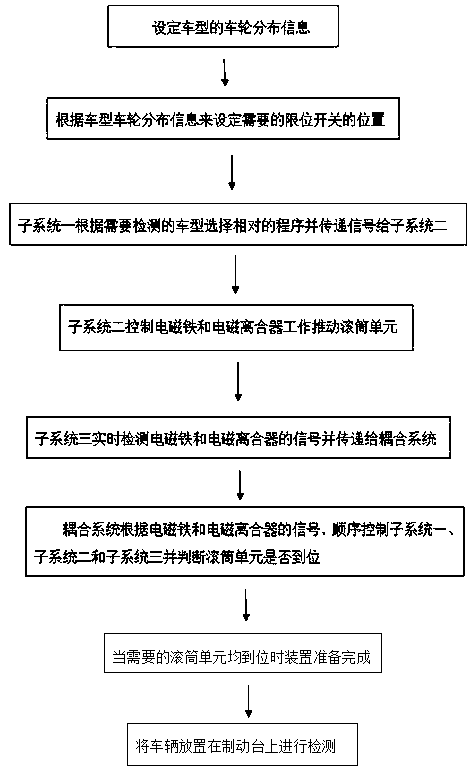
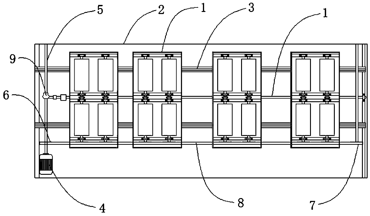
The invention relates to the field of vehicle detection devices, and particularly discloses a self-adaptive adjustment method for a truck brake table and a roller brake table for detection. The methodcomprises the steps that S1, a program is preset according to different vehicle types to determine the positions, needed by the corresponding vehicle types, of roller units on a roller brake table; S2, a subsystem I selects a preset program according to the vehicle model and transmits a signal to a subsystem II; S3, the subsystem II adjusts the position of the roller unit according to the signalof the subsystem I; S4, when detecting that a corresponding limiting switch is triggered, a subsystem III transmits a signal to the system II to enable a corresponding electromagnet to be powered off;S5, a coupling system detects electric signals of an electromagnet, an electromagnetic clutch and the limiting switch in real time and judges whether the roller unit is in place or not; and S6, the vehicle is placed on a brake table to be detected, and detected data are obtained. The method has the advantages that the position of the roller unit can be changed to adapt to different vehicle types,and the adaptability of the device is improved.

Description

technical field [0001] The invention relates to the field of vehicle detection devices, in particular to an adaptive adjustment method for a truck braking platform and a detection roller braking platform. Background technique [0002] According to the implementation regulations of China's Road Traffic Safety Law, trucks and large and medium-sized non-operating passenger vehicles shall be inspected once a year within 10 years, and once every 6 months if they exceed 10 years. Traffic accidents, so it is necessary to regularly detect the braking force of the car. During the inspection, it is necessary to use a brake table to detect the braking performance of the car and the condition of the vehicle wheels. The existing roller detection table has limited rollers, and It is a fixed setting. Because the wheel distribution and the distance between the wheels of different models are different, it is necessary to use the brake table to adapt to different models. It has achieved the p...

Claims


Application Information

Patent Timeline
IPC IPC(8): G01M17/007
CPCG01M17/007
Inventor 宋新民陶雪松
Owner 成都成保发展股份有限公司
Learn More