
Ceiling lamp

A ceiling fan lamp and fan technology, applied in the field of ceiling fan lamps, can solve the problems of insufficient blade smoothness, large tooth resistance, cumbersome installation, etc., and achieve the effects of smooth display and storage, smooth and stable improvement, and simple structure

Pending Publication Date: 2018-08-31
ZHONGSHAN BAOSHAN ELECTRICAL APPLIANCE CO LTD
View PDF1 Cites 0 Cited by
  • Summary
  • Abstract
  • Description
  • Claims
  • Application Information

AI Technical Summary

Problems solved by technology

However, the ceiling fan lamp with the above-mentioned structure has the following disadvantages: (1) the blades are installed on the blade support member together through the pivot shaft, the planetary gear and the sun gear, which has a complex structure, high cost, and cumbersome installation; (2) due to The blades are on the rotating disk, and the synchronous sliding and retracting storage needs to be driven by the meshing rotation of the planetary gear and the sun gear, which will generate a lot of noise during operation, and the resistance of the teeth is large, and the sliding and retracting of the blades for storage Insufficient smoothness, easy to wear and short life

Method used


Image

  • Ceiling lamp
  • Ceiling lamp
  • Ceiling lamp

Examples


Embodiment 1

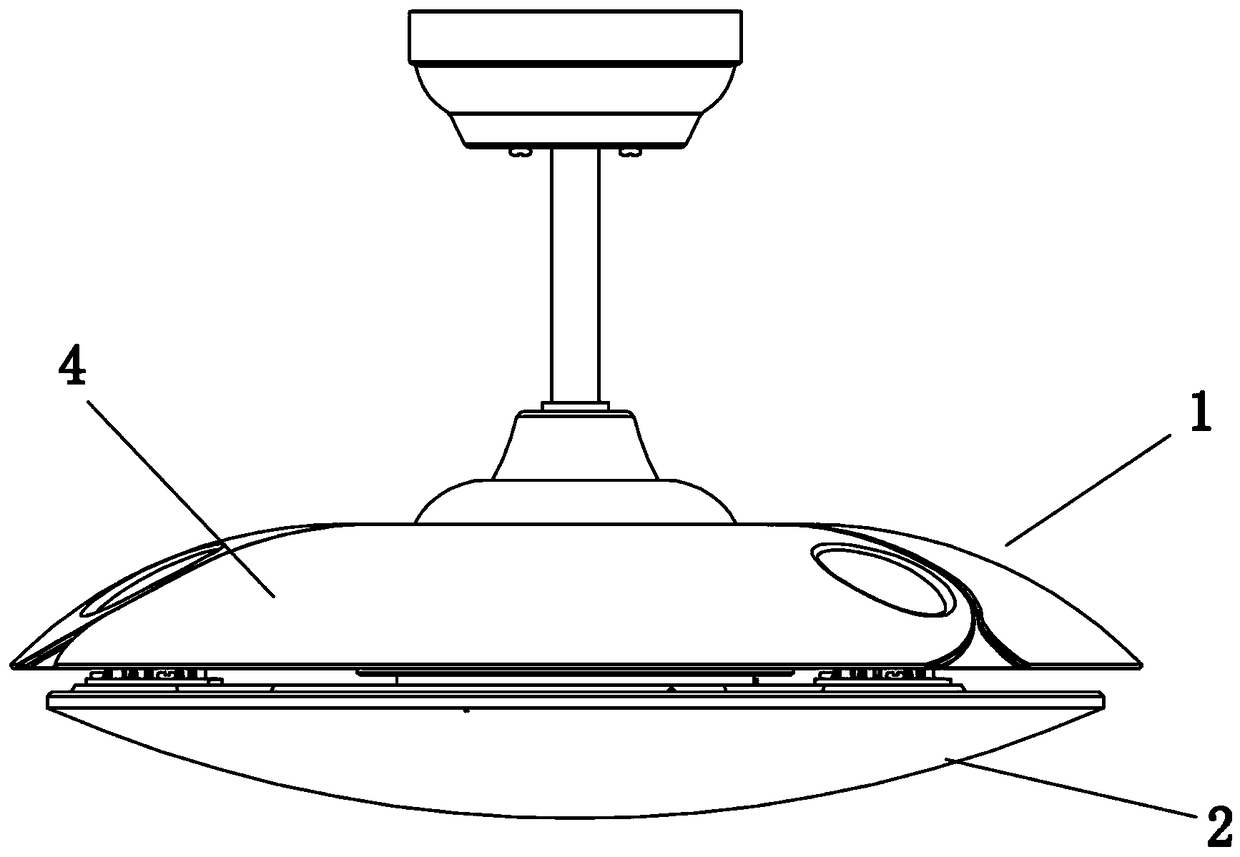
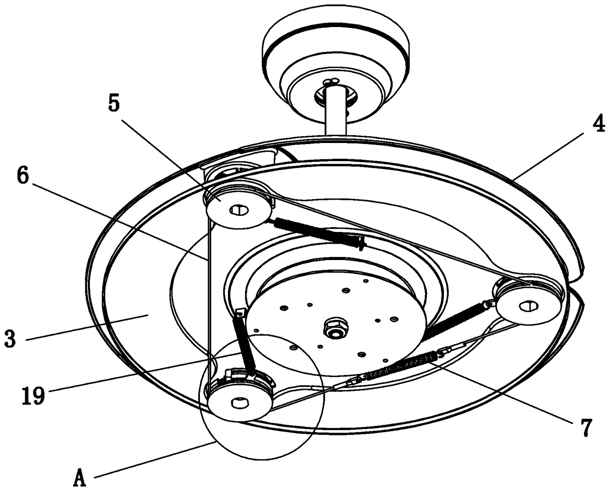
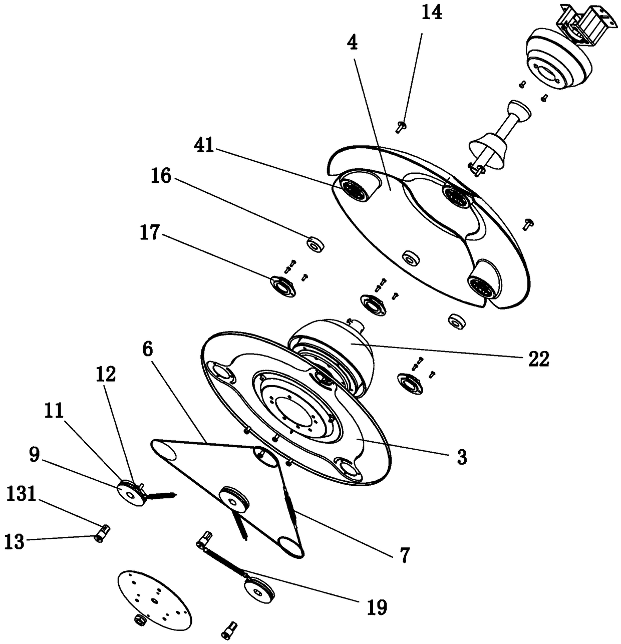
[0041] Embodiment one: if Figure 1 to Figure 10 As shown, a ceiling fan lamp includes a fan part 1 and a lamp part 2. The fan part 1 includes a rotating disk 3, at least two fan blades 4 and at least two sets of rotating wheel assemblies 5, and each fan blade 4 passes through Each group of rotating wheel assemblies 5 is installed on the rotating disk 3, and is characterized in that it also includes a synchronous rope 6, and the synchronizing rope 6 is wound on each group of synchronizing wheel assemblies 5, so that each fan blade 4 is positioned on the rotating disk. 3, synchronously slide out and synchronously retract for storage, and the synchronous rope 6 is also provided with an elastic member 7, and the elastic member 7 is connected to both ends of the synchronous rope 6. In this embodiment, the elastic member 7 is Extension spring, the two ends of the extension spring are respectively connected to the two ends of the synchronous rope 6.

[0042] As a more specific soluti...

Embodiment 2

[0049] Embodiment two: if Figure 11 As shown, this embodiment is similar to the first embodiment above, the only difference is that the elastic member 7 is replaced by a tensioning wheel 8, the tensioning wheel 8 is arranged on the rotating disk 3, and the synchronous rope 6 is wound around On the tensioning pulley 8, the tensioning pulley 8 also plays the role of tightening the synchronous rope to prevent the synchronous rotation between the groups of running wheel assemblies 5 from being loosened due to the synchronous rope 6.

[0050] Working principle: when working, the motor 22 drives the rotating disk 3 to rotate, and the fan blade 4 slides and unfolds under the action of centrifugal force, and drives the rotating wheels 9 to rotate. 18, so that the rotating wheel 9 can rotate within a certain range, so that each fan blade 4 can be slid and displayed synchronously on the rotating disk 3 .

[0051] When the motor 22 is powered off, the rotating disk 3 stops rotating, an...


PUM


Abstract

The invention discloses a ceiling lamp which comprises a fan part and a lamp part, wherein the fan part comprises a rotary disc, at least two fan blades and at least two rotating wheel assemblies; andeach fan blade is mounted on the rotating disc through each rotating wheel assembly. The ceiling lamp is characterized by further comprising a synchronous rope which winds each synchronous wheel assembly, so that the fan blades slide synchronously on the rotating discs to exhibit and retract synchronously to store. According to the ceiling lamp, the rotating wheel assemblies are connected throughthe synchronous rope, so that the rotating wheel assemblies rotate synchronously, and the fan blades slide synchronously on the rotating discs to exhibit and retract synchronously to store. The resistance between the synchronous rope and the rotating wheel assemblies is small, the noise is low and the fan blades are smooth to exhibit and store and are small in wear, and the service life of the product is prolonged obviously. Moreover, the ceiling lamp is simple and reasonable in structure.

Description

technical field [0001] The invention relates to the technical field of ceiling fan lamps. Background technique [0002] Decorative ceiling fans are commonly known as ceiling fan lamps, which are a combination of lamps and ceiling fans, which not only have the lighting and decoration functions of lamps, but also have the blowing effect of fans. At present, the best-seller on the market is a kind of invisible ceiling fan lamp that can hide the blades. The advantage of this invisible ceiling fan lamp is that when the user does not use the fan function, the blades will be automatically retracted and stored on the rotating disk (ie: storage disk ), it does not affect the appearance. When the user uses the fan function, the blades rotate with the rotating disk (ie: the storage disk), and the blades are thrown out of the rotating disk under the action of centrifugal force, that is, the blades slide out. [0003] See Chinese Invention Patent No.: 200680032396.1, title: combined lig...

Claims


Application Information

Patent Timeline
Patent Type & Authority Applications(China)
IPC IPC(8): F04D25/08F04D29/36F04D29/66F21V33/00
CPCF04D25/088F04D29/36F04D29/666F21V33/0096F04D29/362
Inventor 谢刚罗金林
Owner ZHONGSHAN BAOSHAN ELECTRICAL APPLIANCE CO LTD
Learn More