
electrical tools

A technology of electric tools and transmission parts, which is applied in electric components, electromechanical devices, electrical components, etc., can solve problems such as unfavorable maintenance and complex programming code

Active Publication Date: 2022-06-24
MOBILETRON ELECTRONICS
View PDF4 Cites 0 Cited by
  • Summary
  • Abstract
  • Description
  • Claims
  • Application Information

AI Technical Summary

Problems solved by technology

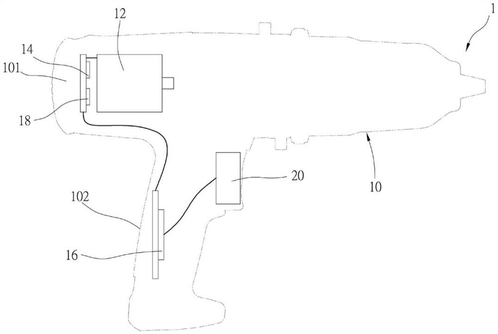
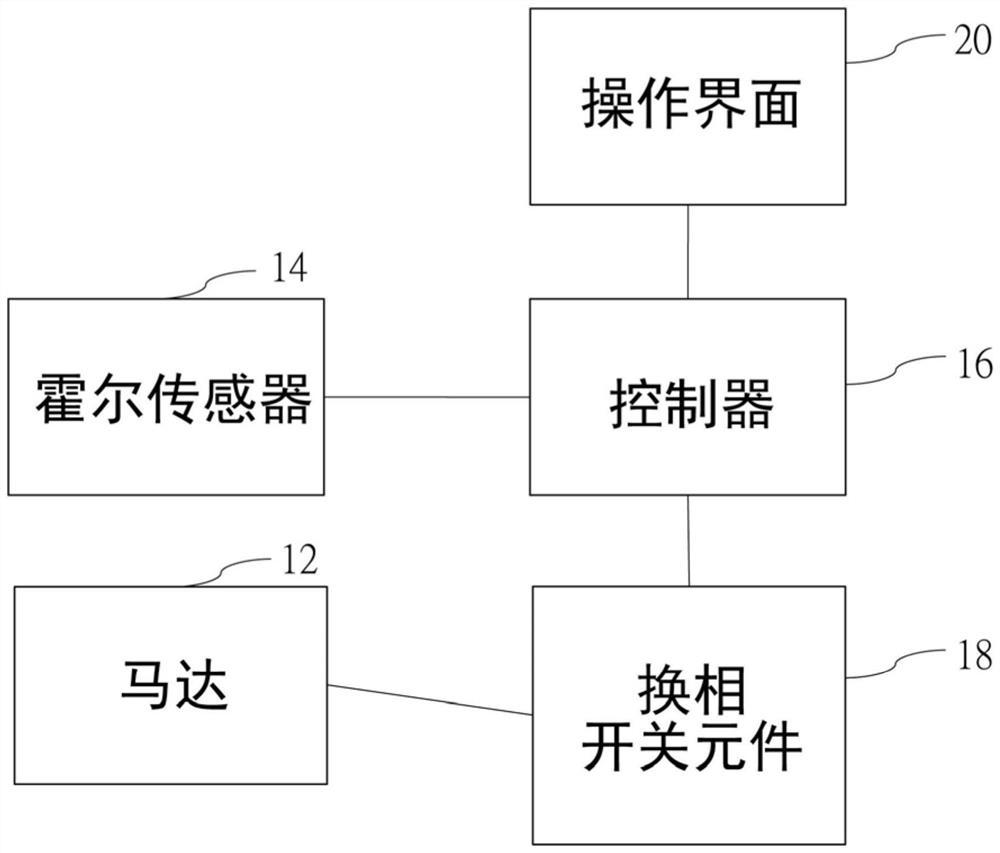
It can be seen from the above that the motor commutation program and user operation program of the conventional electric tool 1 are all calculated by the controller 16, which makes the programming of the controller 16 complicated and unfavorable for maintenance.

Method used


Image

  • electrical tools
  • electrical tools
  • electrical tools

Examples


Embodiment Construction

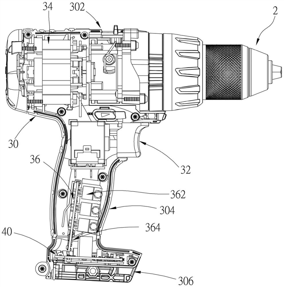
[0017] In order to illustrate the present invention more clearly, preferred embodiments are given and described in detail with the accompanying drawings as follows. Please refer to Figure 3 to Image 6 As shown, a power tool 2 according to a preferred embodiment of the present invention includes a housing 30, a motor 34, a plurality of Hall sensors 38, a first circuit board 36 and a second circuit board 40, wherein:

[0018] The housing 30 includes a transmission portion 302, a handle portion 304 and a bottom portion 306, wherein the handle portion 304 is located between the transmission portion 302 and the bottom portion 306; the transmission portion 302 is provided with a motor 34 and a driving mechanism (not shown in the figure). shown), the rotating shaft of the motor 34 is used to drive the drive mechanism; the hand-held portion 304 is for personnel to hold, and the hand-held portion 304 is provided with an operation interface 32 for the personnel to operate to generate a...


PUM


Abstract

An electric tool includes a casing, a motor, multiple hall sensors, a first circuit board and a second circuit board. The plurality of Hall sensors sense the rotor position of the motor and generate corresponding position information; the first circuit board is provided with a plurality of reversing switch assemblies and a first controller; the second circuit board is provided with a second controller, and the second circuit board is provided with a second controller. The second controller can transmit corresponding driving information to the first controller according to the operation information of the operation interface, and the first controller can control the multiple phase-changing switch assemblies to perform phase-changing according to the driving information and the position information, so that the The rotor of the motor rotates. Through the design of the present invention that the phase change program and the user operation program are processed by two different controllers, the program codes of each controller can be effectively simplified, and the maintenance of the controllers is facilitated.

Description

technical field [0001] The present invention relates to electric tools; in particular, it refers to a design of electric tools which is beneficial to writing and maintaining program codes. Background technique [0002] like figure 1 and figure 2 As shown, the conventional power tool 1 includes a casing 10 , a motor 12 , a Hall sensor 14 , a controller 16 and a commutation switch assembly 18 , wherein the casing 10 includes a transmission part 101 and a hand-held part 102 , and the transmission part 101 A motor 12 and a driving mechanism (not shown) are arranged in the motor 12 , the motor 12 is a three-phase DC brushless motor, and an operation interface 20 is arranged in the hand-held part 102 , and the operation interface 20 is operated by the user to generate an operation information. [0003] The Hall sensor 14 is electrically connected to the controller 16 , and the commutation switch assembly 18 is electrically connected to the motor 12 and the controller 16 respect...

Claims


Application Information

Patent Timeline
Patent Type & Authority Patents(China)
IPC IPC(8): H02K11/215H02K11/25H02K11/33
CPCH02K11/215H02K11/25H02K11/33
Inventor 王士豪黄瑞贞
Owner MOBILETRON ELECTRONICS
Learn More