Vision detection device

A technology of vision detection and box body, which is applied in the direction of eye testing equipment, medical science, diagnosis, etc. It can solve problems affecting testing, power consumption, and cost increase, and achieve simple installation and manufacturing, improve accuracy, and save electricity.

Inactive Publication Date: 2020-08-25
李发标
View PDF7 Cites 0 Cited by
  • Summary
  • Abstract
  • Description
  • Claims
  • Application Information

AI Technical Summary

Problems solved by technology

For the visual mark symbol E on the eye chart for testing eyesight, the opening direction of each row is fixed, and the person whose eyesight is tested is very easy to recite it in advance, so that the measured vision data will not change. True, in addition, the traditional eye chart is also equipped with lighting function, one kind of lighting is set inside, and the other kind of lighting is set outside, and the light inside the eye chart needs to turn on all the internal lights during the test. In addition, there are a large number of lighting lamps, which need to fully cover the entire vision chart and be turned on at the same time, resulting in power consumption; when the lighting is set inside the vision chart, it directly illuminates the surface of the vision chart during the test, which is prone to reflections and affects the test. The irradiation angle of the lighting lamp needs to be set precisely, which leads to an increase in the accuracy of the installation and an increase in the cost

Method used


Image

  • Vision detection device
  • Vision detection device
  • Vision detection device

Examples


Embodiment Construction

[0019] This part will describe the specific embodiment of the present invention in detail, and the preferred embodiment of the present invention is shown in the accompanying drawings. Each technical feature and overall technical solution of the invention, but it should not be understood as a limitation on the protection scope of the present invention.

[0020] In the description of the present invention, it should be understood that the orientation descriptions, such as up, down, front, back, left, right, etc. indicated orientations or positional relationships are based on the orientations or positional relationships shown in the drawings, and are only In order to facilitate the description of the present invention and simplify the description, it does not indicate or imply that the device or element referred to must have a specific orientation, be constructed and operated in a specific orientation, and thus should not be construed as limiting the present invention.

[0021] I...


PUM


Abstract

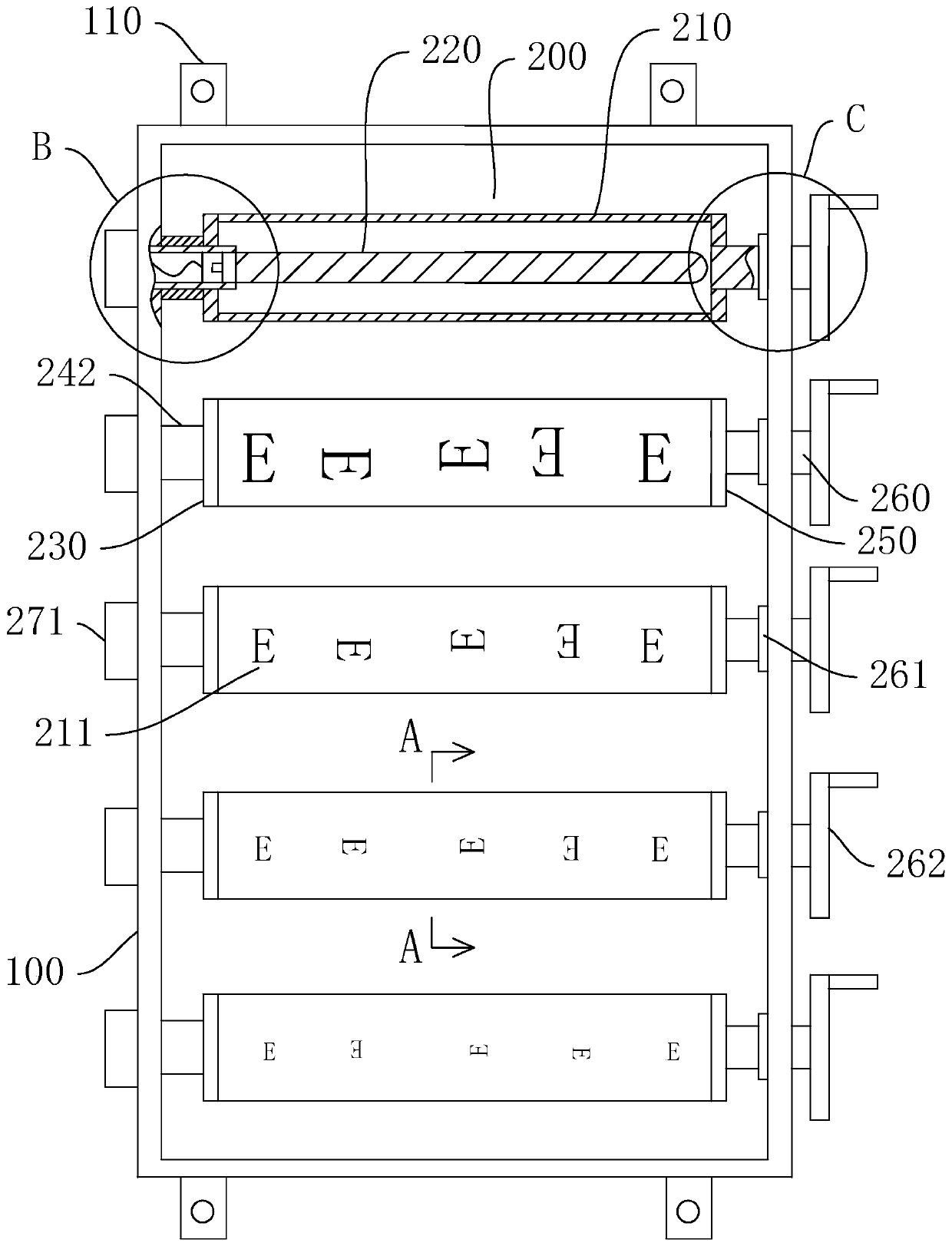
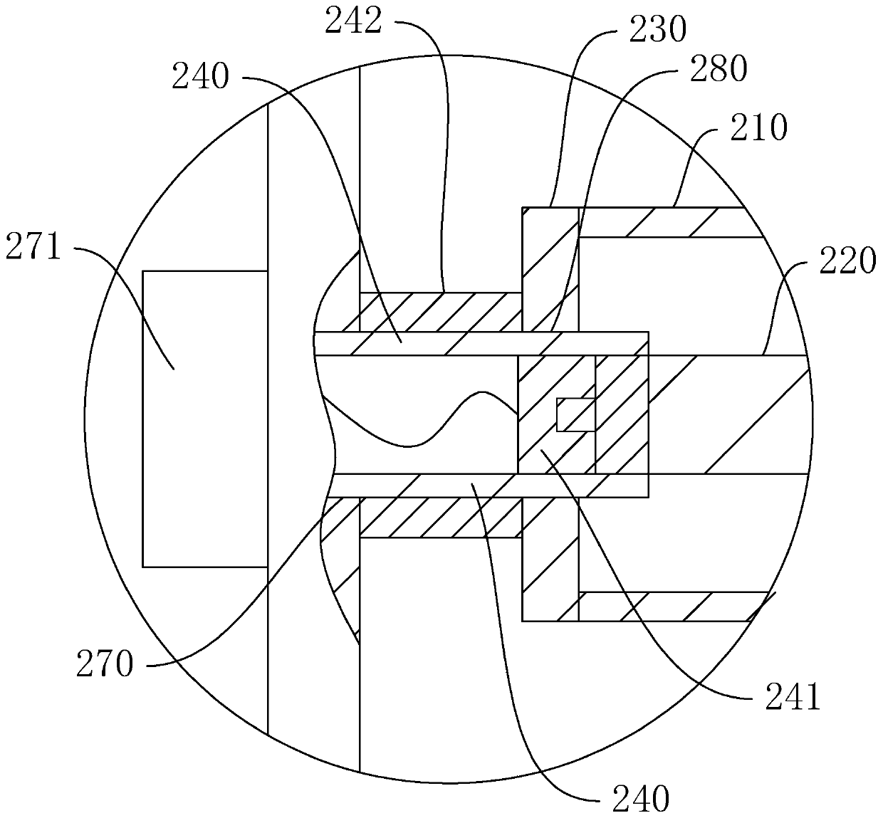
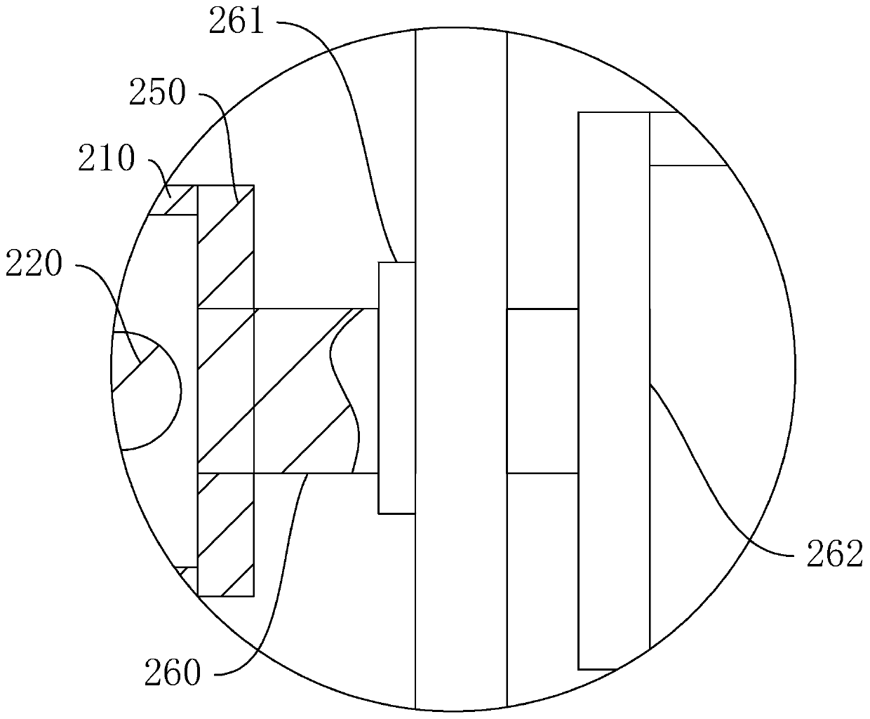
The invention discloses a vision detection device which comprises a box body and a plurality of rotating shell frames; an opening is formed in the front side of the box body; the plurality of rotatingshell frames, each of which comprises four lath-shaped light-transmitting plates, are arranged in the box body up and down at intervals, and the four light-transmitting plates are connected to form the corresponding cuboid-shaped rotating shell frame; a first rotating mechanism and a second rotating mechanism are connected to the left end and right end of each rotating shell frame respectively; the outer side wall of each light-transmitting plate is attached with a visual target symbol; and a lamp tube is installed in each rotating shell frame. By adopting the vision detection device disclosed by the invention, different light-transmitting plates can be switched by rotating the rotating shell frames, so that a direction of the visual symbol on each rotating shell frame is freely adjusted,and the condition that a tester recites a content of a visual chart in advance is avoided; and in addition, by arranging the lamp tube in each rotating shell frame for illumination, firstly, the effect of saving an electric charge is achieved without turning on all the lamp tubes, and secondly, illumination can be achieved no matter what light-transmitting plate is rotated without adjusting an illumination angle, so that use is convenient, and installation and manufacturing are simple.

Description

technical field [0001] The invention relates to the technical field of vision detection, in particular to a vision detection device. Background technique [0002] The eye chart is a picture for testing eyesight. In the traditional eye chart, several lines of letters are printed on the picture (which is the symbol E). The size of the symbol E in each row is different, and the opening direction of the symbol E in each row is Different, visual acuity is determined by the opening direction of the symbol E that can be seen clearly. The visual mark symbol E on the visual acuity chart of the existing visual acuity test, the opening direction of each row is all fixed, and the person whose visual acuity is tested is very easy to recite it in advance, so that the measured visual acuity data cannot be changed. True, in addition, the traditional eye chart is also equipped with lighting function, one kind of lighting is set inside, and the other kind of lighting is set outside, and the ...

Claims


Application Information

Patent Timeline
Patent Type & Authority Applications(China)
IPC IPC(8): A61B3/032
CPCA61B3/032
Inventor 李发标
Owner 李发标
Why Eureka
Try Eureka