Automatic pipe inserting device for surface air cooler box

A surface cooler and automatic technology, which is applied in the field of automatic intubation device of the surface cooler box, can solve the problems of low work efficiency and easy injury to the hands of the staff, and achieve the effects of convenient operation, saving manpower, and simplifying the transportation operation

Inactive Publication Date: 2020-08-25
陈燕霞
View PDF18 Cites 5 Cited by
  • Summary
  • Abstract
  • Description
  • Claims
  • Application Information

AI Technical Summary

Problems solved by technology

[0005] In order to overcome the shortcomings of manual operation when inserting U-shaped copper pipes in the surface cooler box, the work efficiency is low, and the shortcomings of easily injuring the hands of the staff, the technical problem to be solved is to provide an automatic delivery of U-shaped copper pipes , without manual insertion, an automatic intubation device for the surface cooler box that greatly improves work efficiency

Method used


Image

  • Automatic pipe inserting device for surface air cooler box
  • Automatic pipe inserting device for surface air cooler box
  • Automatic pipe inserting device for surface air cooler box

Examples


Embodiment 1

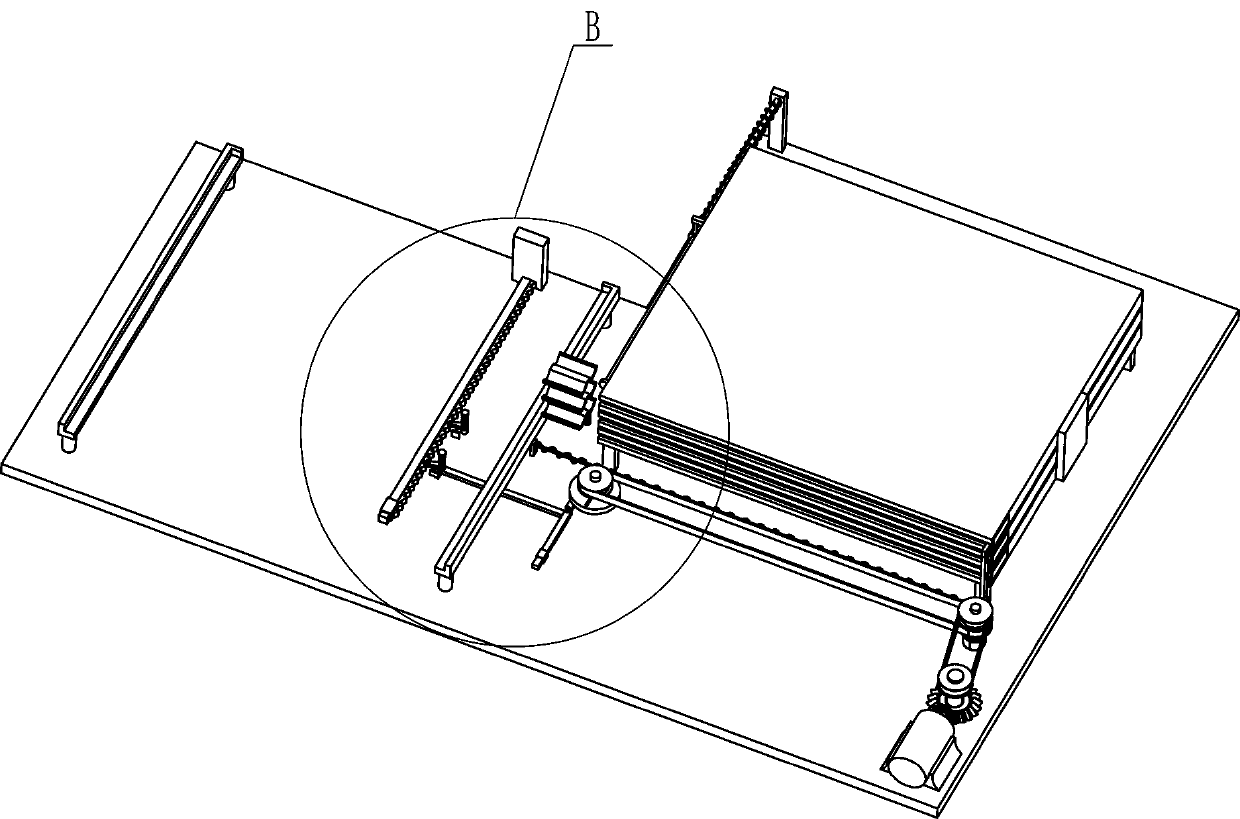
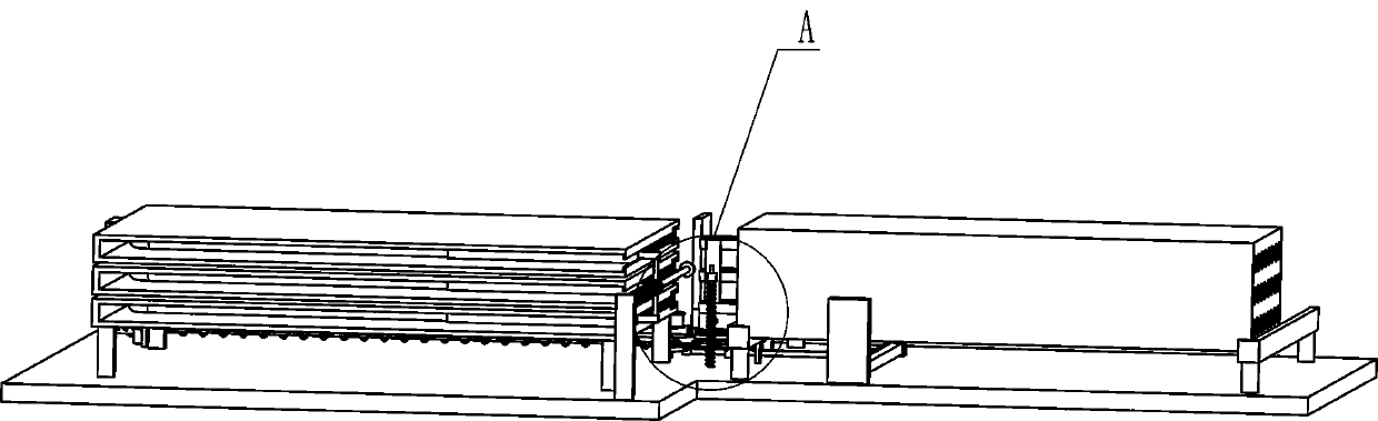
[0030] An automatic intubation device for a surface cooler box, such as figure 1 , figure 2 , image 3 , Figure 4 , Figure 7 and Figure 8 As shown, it includes a base plate 1, a motor 2, a feeding box 3, a first connecting plate 4, a push assembly 6 and a drive assembly 7, the motor 2 is installed on the top front left of the base plate 1, and the right front portion of the base plate 1 There are three feeding boxes 3 for storing U-shaped copper pipes 301 from bottom to top, each feeding box 3 has a chute 302 on the left wall, and a first connecting plate is connected between the front walls of the feeding boxes 3 4. There is an opening 5 on the left side of the front wall of each feeding box 3, and the opening 5 communicates with the chute 302. The driving assembly 7 is installed on the left side of the front part of the bottom plate 1, and the driving assembly 7 is located between the motor 2 and the feeding box 3. Between, the driving assembly 7 is connected with t...

Embodiment 2

[0039] On the basis of Example 1, such as Figure 4 , Figure 5 , Figure 6 and Figure 10 As shown, it also includes a turntable 11, a fixed rod 1101, a first push plate 12, a first support plate 13, a fourth spring 14, a first limit block 15, a torsion spring 16, a special-shaped connecting rod 17, and a first guide sleeve 18. Second connecting rod 19, connecting rod 20, driving pawl 21, reverse locking pawl 2101, second limit block 22, support block 23, fifth spring 24, second guide sleeve 25, ratchet bar 26 and The second push block 27, the rotating disk 11 is installed in the middle part of the vertical rod 77, and the middle part of the vertical rod 77 is connected with a fixed rod 1101. The first push plate 12 and the first support plate 13 are connected in a rotational manner, the first support plate 13 is located under the side of the first push plate 12, and the end of the first support plate 13 is in contact with the side wall of the first push plate 12 A fourth...

Embodiment 3

[0042] On the basis of Example 2, such as figure 1 , Figure 7 and Figure 9 As shown, it also includes a second support plate 28, a second push plate 29, a fourth guide rod 30, a second block 31, a sixth spring 32, a slide block 33, a second fixed block 34, and a first slide bar 35 , the seventh spring 36, the third fixed block 37, the second slide bar 3701, the third push block 38, the eighth spring 39, the first guide wheel 40, the second guide wheel 41 and the stay cord 42, the front of the middle part of the bottom plate 1 The second support plate 28 is installed on the side, and the second support plate 28 is positioned at the front side of the front side L-shaped slide rail 9, and the bottom wall of the second support plate 28 is positioned at the top of the connecting rod 20, and the top of the second support plate 28 is on the right side. A second fixed block 34 is arranged symmetrically on the front and rear sides, and a first slide bar 35 is installed between the ...


PUM


Abstract

The invention relates to a pipe inserting device, and particularly relates to an automatic pipe inserting device for a surface air cooler box. The automatic pipe inserting device for the surface air cooler box aims at achieving the technical purposes that automatic conveying of U-shaped copper pipes can be achieved, manual inserting is not needed, and the work efficiency is greatly improved. The automatic pipe inserting device for the surface air cooler box comprises a bottom plate, a motor, feeding boxes and the like, wherein the motor is arranged on one side of the top of the bottom plate; and the at least three feeding boxes used for storing the U-shaped copper pipes are placed on the side, pointed by the end portion of an output shaft of the motor, of the bottom plate from bottom to top. According to the automatic pipe inserting device, through cooperation of a first push block capable of circularly moving, a first push frame and a second push frame, automatic intermittent conveying of the U-shaped copper pipes in the surface air cooler box can be achieved, when a drive pawl intermittently reciprocates left and right, the surface air cooler box can be driven to automatically replace the pipe inserting position, and through intermittent front-back reciprocating motion of a second push plate, the U-shaped copper pipes can be completely extruded into the surface air cooler box.

Description

technical field [0001] The invention relates to an intubation device, in particular to an automatic intubation device for a surface cooler box. Background technique [0002] The full name of the surface cooler is a surface cooler. The principle is to let the heat medium or refrigerant or refrigerant flow through the inner cavity of the metal pipe, and the air to be treated flows through the outer wall of the metal pipe for heat exchange to achieve the purpose of heating or cooling the air. [0003] In the prior art, the U-shaped copper tubes are manually aligned with the holes on the surface cooler box and inserted one by one. Generally, there are many U-shaped copper tubes that need to be inserted in the surface cooler box, which leads to high labor intensity for people, and they are all Inserting the U-shaped copper pipes one by one, the work efficiency is generally low, and there will be small uneven protrusions on the U-shaped copper pipes, and people's manual insertion...

Claims


Application Information

Patent Timeline
Patent Type & Authority Applications(China)
IPC IPC(8): B23P19/00B23P19/02B23P19/12
CPCB23P19/001B23P19/003B23P19/02B23P19/12
Inventor 莫银彩
Owner 陈燕霞
Why Eureka
Try Eureka