A Rotary Impact Ultrasonic Rock Grinding Device Driven by Single Energy Flow

An impact-type, single-energy technology, applied in the field of deep space exploration, can solve the problems of difficult removal of wear debris, impact of wear debris on grinding efficiency, etc., and achieve the effect of improving rock grinding efficiency, simplifying structure and reducing production costs.

Active Publication Date: 2022-04-12
HARBIN INST OF TECH
View PDF5 Cites 0 Cited by
  • Summary
  • Abstract
  • Description
  • Claims
  • Application Information

AI Technical Summary

Problems solved by technology

[0005] The purpose of the present invention is to solve the problem that with the increase of the grinding depth of the existing impact ultrasonic rock grinding device, the grinding debris is not easy to be removed, and the accumulated grinding debris affects the follow-up grinding efficiency.

Method used


Image

  • A Rotary Impact Ultrasonic Rock Grinding Device Driven by Single Energy Flow
  • A Rotary Impact Ultrasonic Rock Grinding Device Driven by Single Energy Flow

Examples


specific Embodiment approach 1

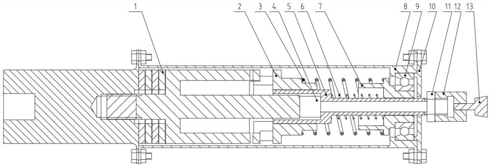
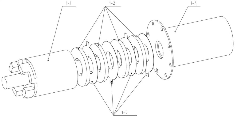
[0022] Specific implementation mode one: combine Figure 1 to Figure 2 Describe this embodiment, a rotary impact type ultrasonic rock grinding device driven by a single energy flow in this embodiment includes a grinding shell assembly, which also includes a longitudinal-torsional composite piezoelectric transducer 1, a rotor 2, a pre- Tight spring 3, free mass block 4, grinding rod 5, recovery spring 6, copper sleeve 7, grinding head connector 12 and grinding head 13, longitudinal-torsional composite piezoelectric transducer 1 is horizontally arranged and connected with the horizontally arranged The front end of the grinding shell assembly is connected, the copper sleeve 7 is installed at the inner rear end of the grinding shell assembly, the grinding rod 5 is horizontally installed in the grinding shell assembly, and the rear end of the grinding rod 5 protrudes from the grinding The shell assembly is connected with the grinding head connector 12, the grinding head 13 is insta...

specific Embodiment approach 2

[0026] Specific implementation mode two: combination figure 1 This embodiment will be described. The longitudinal-torsional composite piezoelectric transducer 1 of this embodiment is connected to the front end of the grinding shell assembly through a flange. With such arrangement, the connection method is simple, easy to disassemble and assemble, and the connection is reliable. Other compositions and connections are the same as in the first embodiment.

specific Embodiment approach 3

[0027] Specific implementation mode three: combination figure 1 This embodiment is described. The grinding shell assembly of this embodiment includes a shell 8, a slewing bearing 9 and an end cover 10. The slewing bearing 9 is set between the inner wall of the shell 8 and the outer wall of the copper sleeve 7. The shell The rear end of 8 is detachably connected with end cover 10. Such arrangement has a simple structure and is convenient for manufacture. Other compositions and connections are the same as those in Embodiment 1 or Embodiment 2.


PUM


Abstract

The utility model relates to a rotary impact ultrasonic rock grinding device driven by a single energy flow, which relates to an ultrasonic rock grinding device. The present invention aims to solve the problem that with the increase of the grinding depth of the existing impact ultrasonic rock grinding device, the grinding debris is not easy to be removed, and the accumulated grinding debris affects the subsequent grinding efficiency. The vertical-torsion composite piezoelectric transducer of the present invention is connected to the front end of the grinding shell assembly, the copper sleeve is installed at the inner rear end of the grinding shell assembly, and the grinding rod is horizontally installed in the grinding shell assembly. The grinding head is installed on the connecting piece of the grinding head, the front end of the grinding rod is in contact with the impact head of the longitudinal-torsional composite piezoelectric transducer through the free mass block, the rotor is sleeved on the front end of the grinding rod, and the preload spring is sleeved on the rotor , the recovery spring is set on the grinding rod, and the rear end of the recovery spring is in contact with the inner end surface of the copper sleeve. The invention is used in the field of deep space exploration.

Description

technical field [0001] The invention relates to an ultrasonic rock grinding device, in particular to a rotary impact ultrasonic rock grinding device driven by a single energy flow, which belongs to the technical field of deep space detection. Background technique [0002] Asteroids are the products left over from the early days of the formation of the solar system 4.5 billion years ago, and have well preserved the information on the early formation and evolution of the solar system. For the deep space exploration of asteroids, the history of the solar system can be better reproduced; in addition, since asteroids may contain a huge amount of mineral and fuel resources, this may be an effective solution to the earth's increasingly scarce various resources. Method. Therefore, deep space exploration is an area in which major aerospace countries invest a lot of manpower and financial resources to compete. At present, the most direct and effective way in the field of deep space ...

Claims


Application Information

Patent Timeline
Patent Type & Authority Patents(China)
IPC IPC(8): B24B1/04B24B41/04B24B47/12B24B47/16G01N1/08
CPCB24B1/04B24B41/04B24B47/12B24B47/16G01N1/08
Inventor 全齐全降文鹤唐德威邓宗全
Owner HARBIN INST OF TECH
Why Eureka
Try Eureka