A hydraulic processing method for glass fiber reinforced plastic products

A technology of hydraulic processing and glass fiber reinforced plastics, applied in manufacturing tools, punching machines, presses, etc., can solve problems such as slow heavy load speed, single slide down speed, and pause.

Active Publication Date: 2021-11-30
江苏扬力液压装备有限公司
View PDF0 Cites 0 Cited by
  • Summary
  • Abstract
  • Description
  • Claims
  • Application Information

AI Technical Summary

Problems solved by technology

[0003] FRP products manufactured by traditional hydraulic machines have the following disadvantages: 1. The opening and closing of the liquid filling valve is not fast enough and unstable; 2. The down speed of the slider is single, which fails to achieve fast no-load speed and slow heavy-load speed. 3. Failure to use accumulators and proportional flow valves makes the transition too hard in the down and return journeys, and there are obvious pauses; 4. The layout of the oil cylinder and tie rods is single, which fails to solve the problem of stress concentration

Method used


Image

  • A hydraulic processing method for glass fiber reinforced plastic products
  • A hydraulic processing method for glass fiber reinforced plastic products
  • A hydraulic processing method for glass fiber reinforced plastic products

Examples


Embodiment Construction

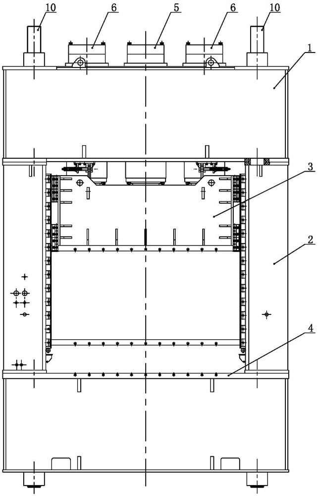
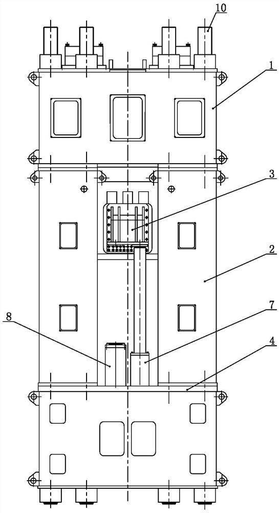
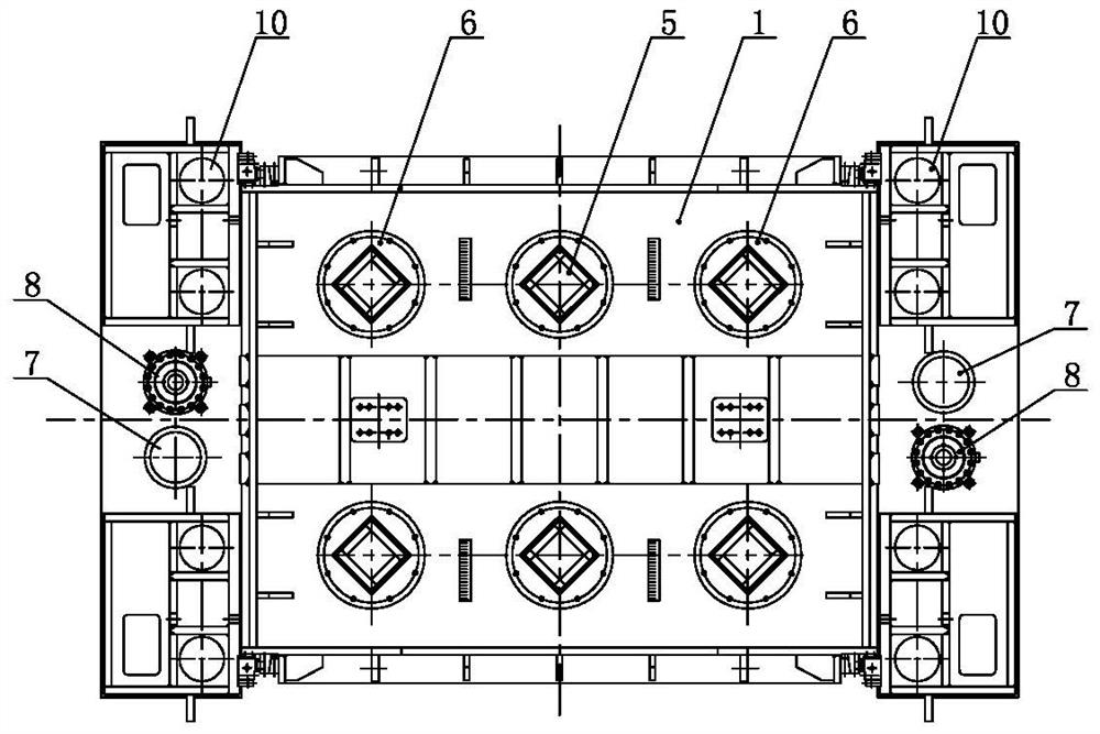
[0022] Such as Figure 1 to Figure 4 As shown, the hydraulic machine used in the present invention includes a workbench 4, four corners of the workbench 4 are equipped with columns 2, and the tops of the front and back rows of columns are connected to each other by the upper beam 1 extending in the left-right direction respectively, and each column's The front part and the rear part are respectively plugged with pull rods 10, and the upper ends of each pull rod 10 pass through the top of the upper beam 1 and are fixed on the upper beam 1 by upper nuts, and the lower ends of each pull rod 10 pass through the bottom of the workbench 4 respectively. and fixed on the workbench by the lower nut; the middle part of the upper crossbeam 1 is respectively equipped with middle cylinders 5, and the left and right sides of the middle cylinder 5 are respectively symmetrically installed with side cylinders 6, and the lower ends of the plungers of each middle cylinder 5 and side cylinder 6 B...


PUM


Abstract

The present invention relates to a hydraulic processing method for FRP products. Each working cycle includes the following steps in turn: (1) slide down quickly: pressure oil enters the middle cylinder and side cylinder, and at the same time, the return cylinder communicates with the oil tank, and the slide moves down rapidly; (2) slide Block slow pressurization: the middle cylinder is pressed separately, the side cylinder is pressed separately, the middle cylinder or the side cylinder is pressed separately first, and then other cylinders are jointly pressed, and the return cylinder provides support and back pressure; (3) the slider maintains pressure; (4) the slider releases pressure : The middle cylinder and side cylinders communicate with the oil tank; (5) Mold opening cylinder ejection: pressure oil enters the lower chamber of the mold opening cylinder, the upper chamber of the mold opening cylinder returns oil to the fuel tank, and the piston rod of the mold opening cylinder pushes the slider up for a certain distance , so that the upper mold and the lower mold can be separated; ⑹ slider return: pressure oil enters the return cylinder, and the slider goes up; ⑺ mold opening cylinder returns: pressure oil enters the upper chamber of the mold opening cylinder, so that the piston rod of the mold opening cylinder retracts , The lower cavity of the mold opening cylinder returns oil to the oil tank. The present invention can adopt different tonnage pressing processes, has high working efficiency and good product quality.

Description

technical field [0001] The invention relates to a hydraulic machine, in particular to a hydraulic processing method for FRP products, and belongs to the technical field of hydraulic machine tools. Background technique [0002] FRP products have the characteristics of light weight, high strength, corrosion resistance, and heat insulation. They are in the leading position of high-tech development in various industries of the national economy, and are one of the main development directions for traditional industrial technology structure and product structure adjustment. At present, the hydraulic processing methods of FRP products in the world all adopt a single hydraulic transmission form, and the main structure generally adopts three typical structures of four-column type, combined frame type or integral frame type, in which the pressing stroke and closing height of the slider are determined by It is determined by the specifications of the main pressing cylinder. Usually, the...

Claims


Application Information

Patent Timeline
Patent Type & Authority Patents(China)
IPC IPC(8): B30B1/34B30B15/00B30B15/04B30B15/16B30B15/26B29C70/42B29C70/54F15B11/17
CPCB29C70/42B29C70/54B30B1/34B30B15/0052B30B15/04B30B15/163B30B15/26F15B11/17F15B2211/20576F15B2211/40576F15B2211/71
Inventor 乔礼惠
Owner 江苏扬力液压装备有限公司
Why Eureka
Try Eureka