
A tilt camera route laying method and device

A technology of tilting the camera and flight path, which is applied in the direction of measuring devices, surveying and navigation, instruments, etc., and can solve problems such as loopholes

Active Publication Date: 2022-03-22
CHINA TOPRS TECH +1
View PDF7 Cites 0 Cited by
  • Summary
  • Abstract
  • Description
  • Claims
  • Application Information

AI Technical Summary

Problems solved by technology

[0004] The currently used route laying method mainly refers to the relevant specifications of framed aerial photography, but the relevant specifications of this framed aerial photography are formulated for the needs of vertical photography. If it is applied to real 3D aerial photography , due to the angle between the tilted camera and the vertical camera, there will be loopholes simply based on the expansion of the vertical image range

Method used

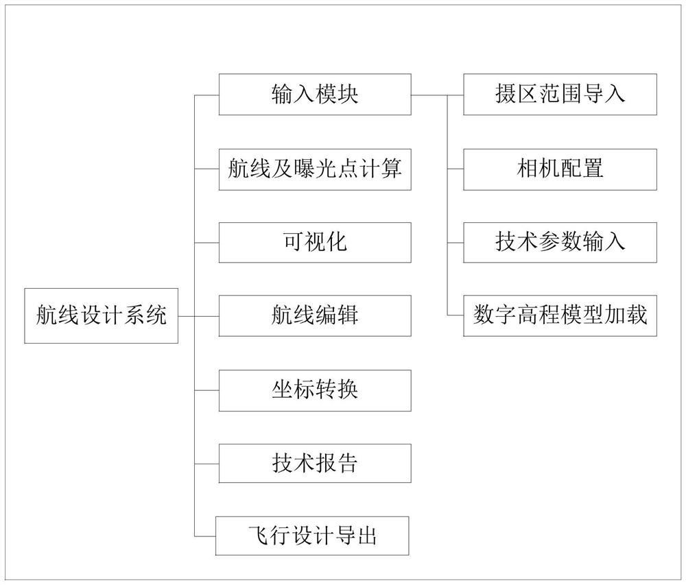

Image

  • A tilt camera route laying method and device
  • A tilt camera route laying method and device
  • A tilt camera route laying method and device

Examples


Embodiment Construction

[0060] In order to make the purpose, technical solutions and advantages of the embodiments of the present application clearer, the technical solutions in the embodiments of the present application will be clearly and completely described below in conjunction with the drawings in the embodiments of the present application. Obviously, the described embodiments are only It is a part of embodiments of the present invention, but not all embodiments. The components of the embodiments of the application generally described and illustrated in the figures herein may be arranged and designed in a variety of different configurations. Accordingly, the following detailed description of the embodiments of the invention provided in the accompanying drawings is not intended to limit the scope of the claimed invention, but merely represents selected embodiments of the invention. Based on the embodiments of the present invention, all other embodiments obtained by those skilled in the art withou...


PUM


Abstract

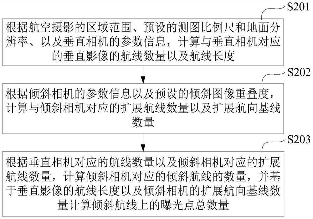
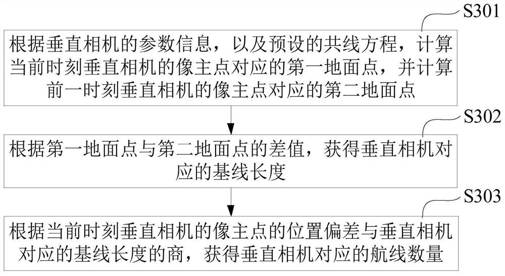
The present application provides a method and device for laying an inclined camera route, wherein the method includes: according to the area range of aerial photography, the preset mapping scale and ground resolution, and the parameter information of the vertical camera, calculate the corresponding vertical camera The number of routes and route length of the vertical image; according to the parameter information of the tilt camera and the preset tilt image overlap, calculate the number of extended routes and the number of extended course baselines corresponding to the tilt camera; according to the number of routes corresponding to the vertical camera and the tilt camera For the corresponding number of extended courses, calculate the number of inclined courses corresponding to the inclined camera, and calculate the total number of exposure points on the inclined course based on the course length of the vertical image and the number of extended course baselines of the inclined camera. In the embodiment of the present application, the route of the tilted camera is laid out in the above manner, so that the obtained aerial image will not cause loopholes due to the angle between the tilted camera and the vertical camera.

Description

technical field [0001] The invention relates to the technical field of aerial photogrammetry, in particular to a method and device for laying a tilt camera route. Background technique [0002] In aerial photography, in order to meet the production needs of real-scene 3D images, real-scene 3D aerial photography is required when photographing the target, that is, to obtain photographic images of the top of the target and photographic images of the side of the target at the same time. At present, during aerial photography, the method of simultaneously carrying out vertical and oblique photography is generally adopted to realize this photographic purpose. In this method, the main optical axis of the vertical camera used to realize vertical imaging is kept parallel to the vertical line, and a vertical image is generated during aerial imaging; the main optical axis of multiple tilt cameras used to realize oblique imaging is parallel to the vertical The lines form a certain angle,...

Claims


Application Information

Patent Timeline
Patent Type & Authority Patents(China)
IPC IPC(8): G01C11/00
CPCG01C11/00
Inventor 李英成齐艳青刘晓龙朱祥娥罗祥勇
Owner CHINA TOPRS TECH
Learn More