
Device for testing thermal response speed of shape memory material

A memory material and thermal response technology, applied in the direction of applying stable tension/pressure to test the strength of materials, measuring devices, analyzing materials, etc., can solve the problems that the thermal response speed cannot be directly fed back, and achieve the effect of easy installation

Pending Publication Date: 2020-08-25
ZHEJIANG SCI-TECH UNIV
View PDF8 Cites 0 Cited by
  • Summary
  • Abstract
  • Description
  • Claims
  • Application Information

AI Technical Summary

Problems solved by technology

However, neither of these two experimental instruments can directly feed back the shape memory material and its thermal response speed under different loads

Method used


Image

  • Device for testing thermal response speed of shape memory material
  • Device for testing thermal response speed of shape memory material
  • Device for testing thermal response speed of shape memory material

Examples


Embodiment 1

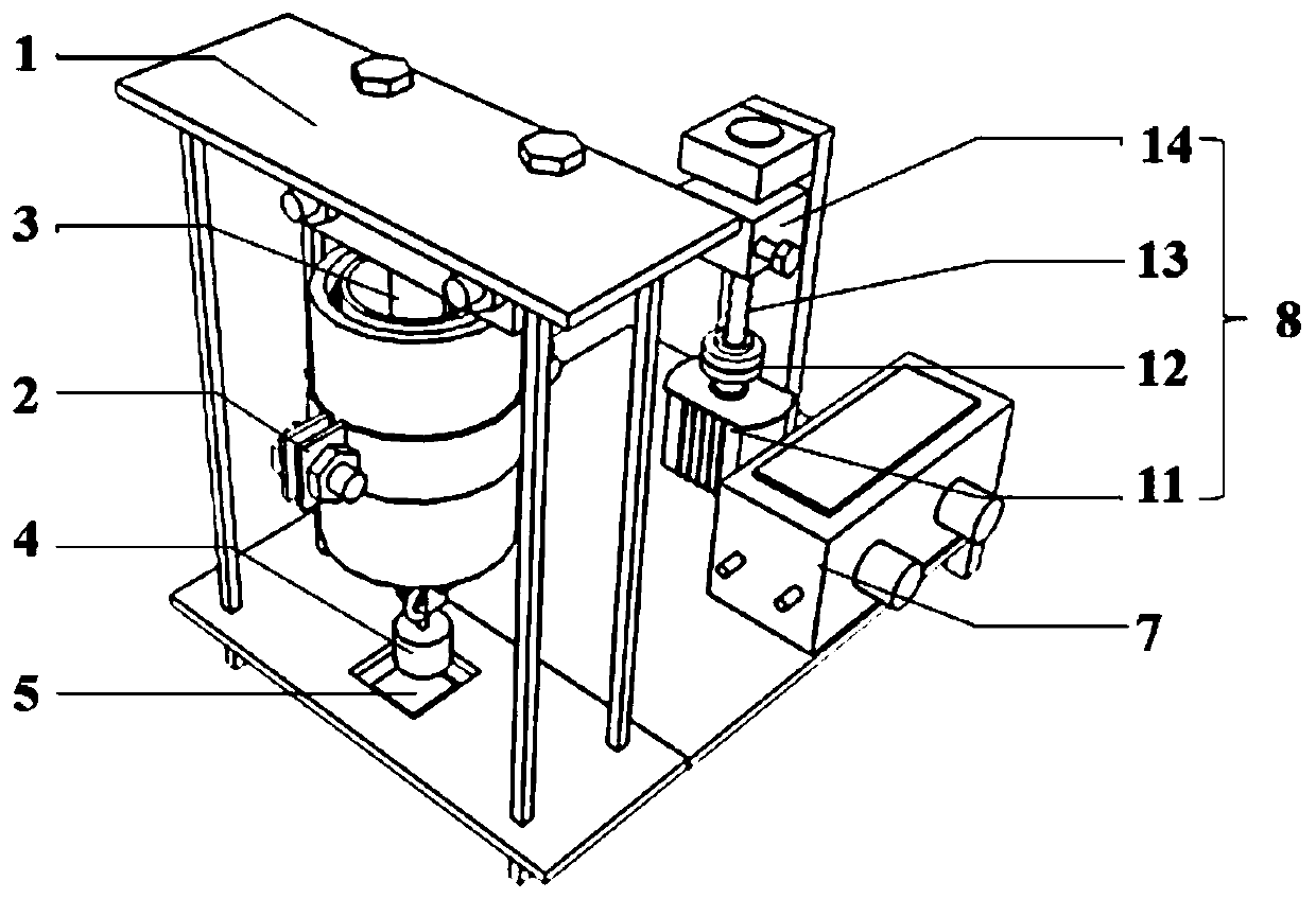
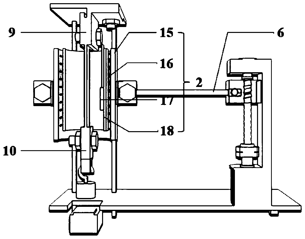
[0030] Such as figure 1 with 2 As shown, the device for testing the thermal response speed of shape memory materials in this embodiment includes a frame 1, a heating cylinder 2, a load weight 4, a displacement sensor 5, an adjustable voltage stabilized power supply 7, a lifting mechanism 8, an upper clamp 9 and Lower fixture 10.

[0031] The frame 1 is a vertical frame structure, including a bottom plate, a top plate and a column between the bottom plate and the top plate. The upper fixture 9 is fixedly installed on the top plate of the frame 1, the upper fixture 9 is used to clamp and fix the top of the test sample 3, the bottom of the test sample 3 is clamped and fixed with the lower fixture 10, and the load weight 4 is hoisted on the lower fixture 10 , so that the test sample 3, the lower clamp 10 and the load weight 4 are in a suspended state under the action of gravity. Wherein, the lower clamp 10 is preferably a U-shaped clamp, which facilitates switching of load weig...

Embodiment 2

[0041] The difference between the device for testing the thermal response speed of the shape memory material in this embodiment and the first embodiment is that:

[0042] The heating cylinder of this embodiment is directly fixed and installed in the middle of the frame, the setting of the lifting mechanism can be omitted, and the test of the thermal response speed of the shape memory material can also be realized, which simplifies the structure of the device and lowers the cost.

[0043] Other structures can refer to Embodiment 1.

Embodiment 3

[0045] The difference between the device for testing the thermal response speed of the shape memory material in this embodiment and the first embodiment is that:


PUM

PropertyMeasurementUnit
diameteraaaaaaaaaa
thicknessaaaaaaaaaa

Abstract

The invention belongs to the technical field of material thermodynamic testing, in particular to a device for testing thermal response speed of a shape memory material. The device for testing the thermal response speed of the shape memory material comprises a rack, a heating cylinder, an upper clamp, a lower clamp, a load weight, a displacement sensor and an adjustable stabilized voltage supply, the upper clamp is fixedly installed at the top of the rack and used for clamping one end of the shape memory material, and the other end of the shape memory material is clamped and fixed to the lowerclamp; the heating cylinder is installed in the middle of the rack so that the shape memory material can be arranged in the heating cylinder in a surrounding mode. The load-bearing weight is hoisted on the lower clamp, and the shape memory material, the lower clamp and the load-bearing weight are in a suspended state under the action of gravity; the displacement sensor is arranged below the weightand is used for measuring the movable displacement of the weight; and the adjustable voltage-stabilizing power supply is electrically connected with the heating cylinder. Through the design of a mounting structure among the heating cylinder, the upper clamp, the lower clamp, the load weight, the displacement sensor and the adjustable stabilized power supply, the test of the thermal response speedof the shape memory material is realized.

Description

technical field [0001] The invention belongs to the technical field of material thermodynamic testing, in particular to a device for testing the thermal response speed of shape memory materials. Background technique [0002] Shape memory materials are a class of smart solid materials that are endowed with various intermediate forms under certain conditions, such as temperature, light, magnetism, electricity, and solvents, and can be restored to their original forms by receiving external stimuli again. According to the different response modes, shape memory materials can be divided into thermal shape memory materials, photoinduced shape memory materials, magnetic shape memory materials, and electrical shape memory materials. Among them, thermotropic shape memory materials can collect the thermal energy of the environment and convert it into kinetic energy for their own shape recovery by virtue of their unique thermodynamic properties. Thermotropic shape memory materials are ...

Claims


Application Information

Patent Timeline
Patent Type & Authority Applications(China)
IPC IPC(8): G01N3/14G01N3/18G01N3/06
CPCG01N3/14G01N3/18G01N3/068G01N2203/0033G01N2203/0057G01N2203/0641
Inventor 徐路董余兵朱曜峰傅雅琴
Owner ZHEJIANG SCI-TECH UNIV
Learn More