A road milling machine

A milling machine and milling technology, which is applied in the field of road milling machines, can solve the problems of inability to adjust and the limited variation range of the milling drum speed, and achieve the effect of improving milling efficiency

Active Publication Date: 2020-05-22
田利彬
View PDF8 Cites 0 Cited by
  • Summary
  • Abstract
  • Description
  • Claims
  • Application Information

AI Technical Summary

Problems solved by technology

[0003] The existing milling machine includes a frame and a milling device, and the milling device includes a milling drum, etc., and the milling speed is changed by changing the speed of the milling device. Most of the existing technologies realize the speed of the milling drum by changing the engine speed However, the change range of the milling drum speed achieved by the change of the engine speed is limited, and it cannot be adjusted effectively according to actual needs.

Method used


Image

  • A road milling machine
  • A road milling machine
  • A road milling machine

Examples


Embodiment Construction

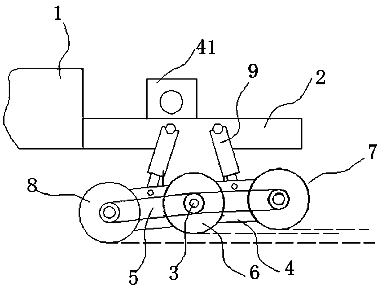
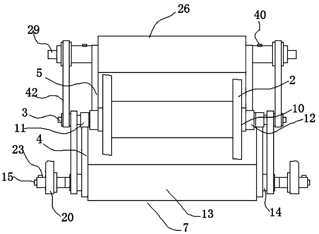
[0028] Such as figure 1 , figure 2 As shown, a road milling machine includes a frame 1 and a lifting seat 2, and a lifting drive mechanism is arranged between the frame 1 and the lifting seat 2. The lifting drive mechanism can adopt a hydraulic lifting mechanism, and the hydraulic The cylinder is fixedly installed on the frame, the piston rod of the hydraulic cylinder is fixedly installed on the lifting seat, and a guide column can also be fixedly installed on the frame, and a guide sleeve cooperating with the guide column is installed on the lifting seat , the lifting base 2 is rotatably mounted with a rotating shaft 3, and the lifting base 2 is also coaxially rotatably mounted with a first swing housing 4 and a second swing housing 5, and the first swing housing 4 and the The rotation axes of the second swing housing 5 are coincident, the rotation axes of the first swing housing 4 and the second swing housing 5 are coincident with the axis of the rotation shaft, and the ro...


PUM


Abstract

The invention relates to a milling machine for a pavement. The milling machine comprises a rack and a lifting base, a lifting driving mechanism is arranged between the rack and the lifting base, and arotation shaft is rotatably installed on the lifting base; a first swing shell and a second swing shell are further rotatably coaxially installed on the lifting base, a middle milling roller is fixedly installed on the rotation shaft, and a first milling roller is rotatably installed at the swing end of the first swing shell; a second milling roller is rotatably installed at the swing end of thesecond swing shell, the rotation shaft is in belt transmission connection with a rotary shaft of the first milling roller and a rotary shaft of the second milling roller, swing driving hydraulic cylinders are hinged between the first swing shell and the lifting base as well as between the second swing shell and the lifting base respectively, and a rotation driving mechanism for driving the rotation shaft to rotate is further installed on the lifting base. The first milling roller, the middle milling roller and the second milling roller can be located at different height positions while millingoperation is conducted, and the milling efficiency can be effectively improved.

Description

technical field [0001] The invention relates to a road milling machine. Background technique [0002] Road milling machine is one of the main types of asphalt pavement maintenance construction machinery and one of the main equipment for asphalt concrete pavement maintenance construction. It can be used to remove defects such as pavement wrapping, oil waves, reticulation, ruts, etc. It can also be used to excavate road pits and grooves, as well as roughening of cement pavement and milling of surface layer dislocation. [0003] The existing milling machine includes a frame and a milling device, and the milling device includes a milling drum, etc., and the milling speed is changed by changing the speed of the milling device. Most of the existing technologies realize the speed of the milling drum by changing the engine speed However, the change range of the milling drum speed realized by the change of the engine speed is limited, and it cannot be effectively adjusted according ...

Claims


Application Information

Patent Timeline
Patent Type & Authority Patents(China)
IPC IPC(8): E01C23/08E01C23/088
CPCE01C23/08E01C23/088
Inventor 田利彬冯士杰贺俊利吕东刘昕昀陈蕊姗刘进祥闫俊喜赵蔚雄郭万江
Owner 田利彬
Why Eureka
Try Eureka