Display device and preparation method thereof

A display device and display panel technology, applied in nonlinear optics, instruments, optics, etc., can solve problems such as poor bonding, poor bonding of foam double-sided adhesives, and easy flow of glue into the display area, etc., to save width and solve problems. The effect of poor adhesion

Pending Publication Date: 2020-08-25
BOE TECH GRP CO LTD +1
View PDF6 Cites 0 Cited by
  • Summary
  • Abstract
  • Description
  • Claims
  • Application Information

AI Technical Summary

Problems solved by technology

[0005] In order to realize the ultimate frameless appearance effect of the display device, the inventors of the present invention proposed a structural design of the display device, in which the display panel is directly bonded to the upper surface of the bent part of the back plate by optically transparent resin (OCR) glue , and the adhesive layer is used to wrap the side periphery of the display panel, which can save the outer middle frame, not only realize the distance from the display area to the edge of the display device is less than 1mm, but also solve the problem of double foam foam in the existing front frameless design. The surface glue is not firmly bonded, or the glue is easy to flow into the display area, resulting in poor display technical problems

Method used


Image

  • Display device and preparation method thereof
  • Display device and preparation method thereof
  • Display device and preparation method thereof

Examples


Embodiment Construction

[0048] The following describes the embodiments of the present invention in detail, and those skilled in the art will understand that the following embodiments are intended to explain the present invention, and should not be regarded as limiting the present invention. Unless otherwise specified, in the following examples that do not explicitly describe specific techniques or conditions, those skilled in the art can carry out according to commonly used techniques or conditions in this field or according to product instructions.

[0049] In one aspect of the invention, the invention provides a display device.

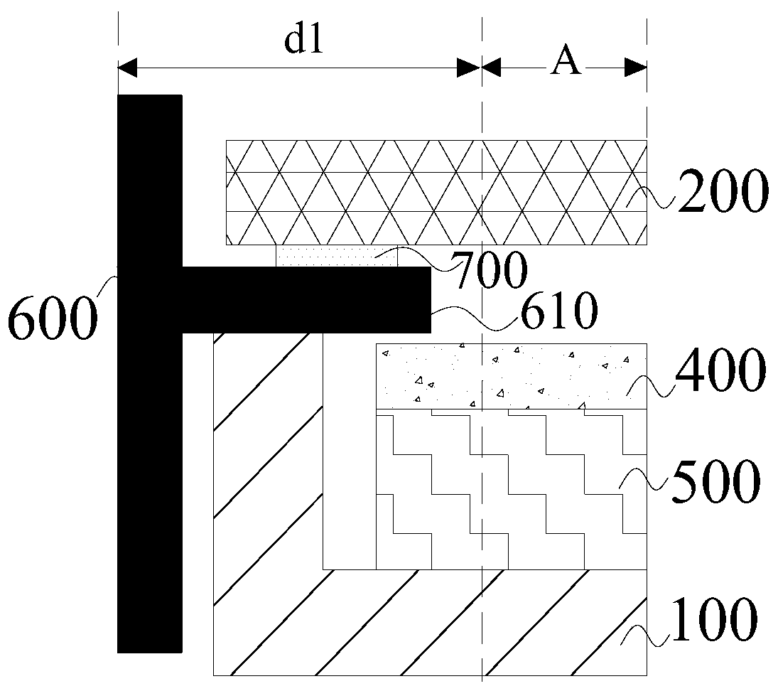
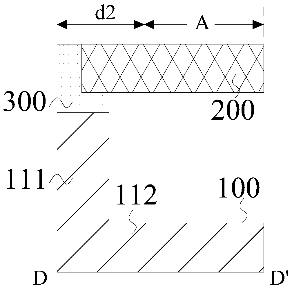
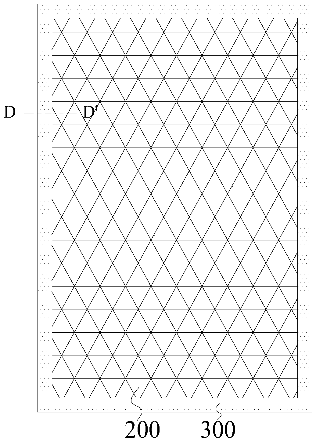
[0050] According to an embodiment of the present invention, refer to figure 2 , the display device includes a backplane 100, a display panel 200, and an adhesive layer 300; wherein, the backplane 100 has an L-shaped bent portion, and the bent portion includes a side plate 111 and a bottom plate 112, wherein the side plate 111 has oppositely disposed The inner surface and...


PUM


Abstract

The invention provides a display panel and a manufacturing method thereof. The display device includes: a backboard having an L-shaped bent portion including a bottom plate and a side plate; the display panel is arranged on the side, away from the bottom plate, of the side plate, and the orthographic projection of the display panel on the upper surface of the bottom plate partially coincides withthe orthographic projection of the side plate on the upper surface of the bottom plate; the lower surface of the display panel and the upper surface of the side plate are directly bonded through the adhesive layer, and the adhesive layer further makes contact with the side face of the display panel. The invention provides a display device. The lower surface of the display panel is directly bondedwith the upper surface of the side plate of the backboard through the adhesive layer; according to the display device, the double-faced adhesive tape is arranged on the display panel, and the side periphery of the display panel is covered, so that the width of the double-faced adhesive tape can be reduced, a middle frame arranged on the periphery can be further omitted, the perfect frameless appearance effect of the display device is facilitated, and a display area of the display device is close to full-screen design.

Description

technical field [0001] The present invention relates to the field of display technology, in particular, the present invention relates to a display panel and a manufacturing method thereof. Background technique [0002] Generally, most LCD TV structures have a front frame, that is, a backlight, an LCD panel and a front frame are assembled together. However, with the increasing consumption level in the past two years, consumers not only have higher and higher requirements for the performance of LCD TVs, but also higher and higher requirements for appearance. )television. [0003] Among them, the structure of the display device without front frame can refer to figure 1 , the display panel 200 is glued to the extension part 610 of the middle frame 600 by means of foam double-sided adhesive tape 700 so as to omit the traditional front frame. However, the distance d1 from the display area A of this front frameless design to the edge of the display device is usually greater than...

Claims


Application Information

Patent Timeline
IPC IPC(8): G02F1/1333
CPCG02F1/133308G02F1/1333G02F1/133317G02F1/133314G02F2202/28
Inventor 郭俊杰孙志华李建
Owner BOE TECH GRP CO LTD
Why Eureka
Try Eureka