
A kind of circulating powder passing machine for electric wire

A cyclic, powder-passing technology, applied in the manufacture of circuits, electrical components, cables/conductors, etc., can solve the problems of the length of the wiring frame cannot be adjusted, the wires are easily bent, etc., to facilitate the observation of the internal situation, convenient operation, and simple structure. Effect

Active Publication Date: 2021-07-30
鹰潭胜华金属有限责任公司
View PDF9 Cites 0 Cited by
  • Summary
  • Abstract
  • Description
  • Claims
  • Application Information

AI Technical Summary

Problems solved by technology

[0002] At present, when domestic cable manufacturers produce rubber cables, the surface of the rubber wire is cooled and coated with a layer of mica powder, and then wound up on the reel, so as to avoid the adhesion between products. The existing wire powder machine The length of the wiring frame installed at the wire outlet cannot be adjusted. When processing large-sized wires, it cannot support the wires well, causing the problem that the wires are easy to bend. Therefore, we propose a circulating powder powder machine for wires.

Method used

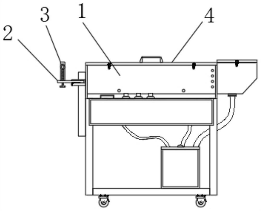

Image

  • A kind of circulating powder passing machine for electric wire
  • A kind of circulating powder passing machine for electric wire
  • A kind of circulating powder passing machine for electric wire

Examples


Embodiment Construction

[0026] The following will clearly and completely describe the technical solutions in the embodiments of the present invention with reference to the accompanying drawings in the embodiments of the present invention. Obviously, the described embodiments are only some of the embodiments of the present invention, not all of them. Based on the embodiments of the present invention, all other embodiments obtained by persons of ordinary skill in the art without making creative efforts belong to the protection scope of the present invention.

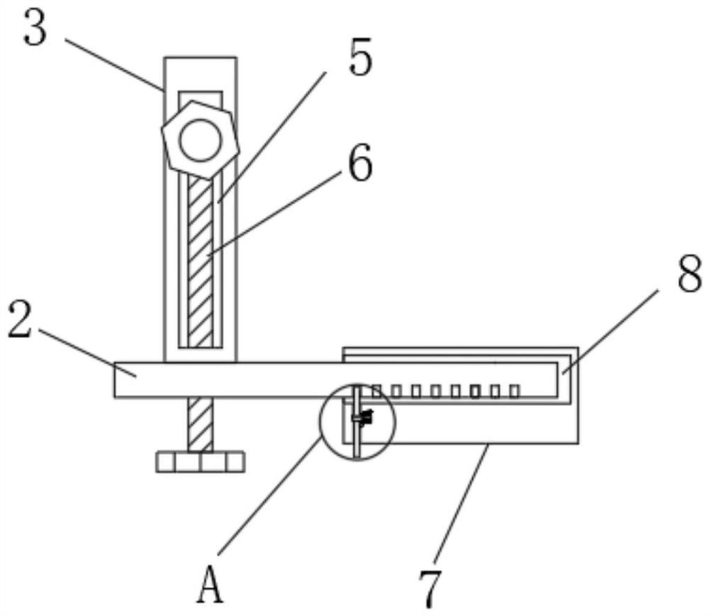
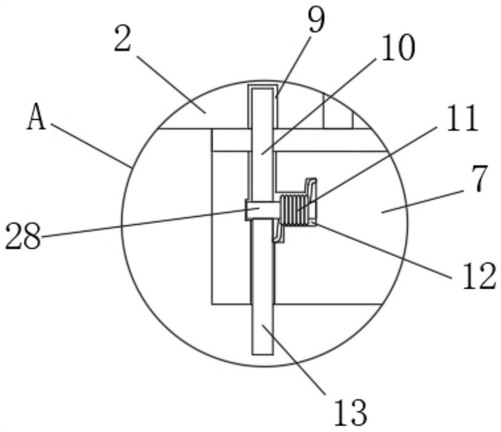
[0027] see Figure 1-Figure 7 , the present invention provides the following technical solutions: a circulating type powder sifting machine for electric wires, including a powder sifting machine main body 1, a telescopic mechanism, a lifting mechanism and a cleaning mechanism, the telescopic mechanism includes a telescopic rod 2, and the telescopic rod 2 is located in the powder sifting machine main body 1 The top of one side, the top of one side...


PUM


Abstract

The invention discloses a circulating type powder-processing machine for electric wires, which comprises a main body of the powder-processing machine, a telescoping mechanism, a lifting mechanism and a cleaning mechanism. The top of one side of the main body of the powder processing machine is fixedly connected with a fixed block, the surface of one end of the fixed block is provided with a second limiting groove, one end of the telescopic rod is inside the second limiting groove, and the inner side of the second limiting groove is One end is provided with a third limiting groove, a block is arranged inside the third limiting groove, a driving lever is arranged at one end of the blocking block, and a second rotating shaft is fixedly connected to the connection between the blocking block and the driving lever. A torsion spring is provided outside one end of the second rotating shaft; compared with the prior art, the present invention has the beneficial effects of: by designing a telescopic mechanism, the length of the telescopic rod can be adjusted to avoid oversized electric wires from passing through the wire frame. There will be a problem of bending, and the application range is wide, and it can be adjusted according to actual needs.

Description

technical field [0001] The invention belongs to the technical field of cable powder-passing devices, and in particular relates to a circulating-type powder-passing machine for electric wires. Background technique [0002] At present, when domestic cable manufacturers produce rubber cables, the surface of the rubber wire is cooled and coated with a layer of mica powder, and then wound up on the reel, so as to avoid the adhesion between products. The existing wire powder machine The length of the wiring frame installed at the wire outlet cannot be adjusted. When processing larger wires, it cannot support the wires well, causing the wires to be easily bent. Therefore, we propose a circulating powder powder machine for wires. Contents of the invention [0003] The object of the present invention is to provide a circulating powder sifting machine for electric wires, so as to solve the problems raised in the above-mentioned background technology. [0004] In order to achieve th...

Claims


Application Information

Patent Timeline
Patent Type & Authority Patents(China)
IPC IPC(8): H01B13/22H01B13/00
CPCH01B13/0036H01B13/22
Inventor 钱尉杨鲜春吕悦
Owner 鹰潭胜华金属有限责任公司
Learn More