Method and device for sending feedback information and method and device for receiving feedback information

A technology for receiving and feeding feedback information, applied in the field of sending feedback information, can solve the problems of increased transmission delay, terminal equipment failing to send feedback information in time, and network equipment failing to know in time, and achieving the goal of reducing transmission delay. Effect

Active Publication Date: 2020-08-25
HUAWEI TECH CO LTD
2 Cites 2 Cited by

AI-Extracted Technical Summary

Problems solved by technology

[0003] In some scenarios, when the terminal device successfully receives the downlink data, the network device may not be able to know the situation in time, for example, in the unlicensed band new radio access technology (new radio access technology unlicensedband, NR-U), the terminal device Failure to send feedback information in time due to fai...

Abstract

The invention provides a method and device for sending feedback information and a method and device for receiving the feedback information. The communication equipment applying the method sends or receives the feedback information through different feedback processes. When the network equipment does not determine whether the previous feedback information is successfully received, the terminal equipment is indicated to use the new feedback process to send the feedback information of the next downlink data, and the next downlink data can be scheduled without waiting for the completion of the processing of the previous feedback information, so that the transmission delay is reduced.

Application Domain

Error prevention/detection by using return channelSignal allocation +1

Technology Topic

Transmission delayEngineering +5

Image

  • Method and device for sending feedback information and method and device for receiving feedback information
  • Method and device for sending feedback information and method and device for receiving feedback information
  • Method and device for sending feedback information and method and device for receiving feedback information

Examples

  • Experimental program(1)

Example Embodiment

[0065] The technical solutions in the present application will be described below with reference to the accompanying drawings.
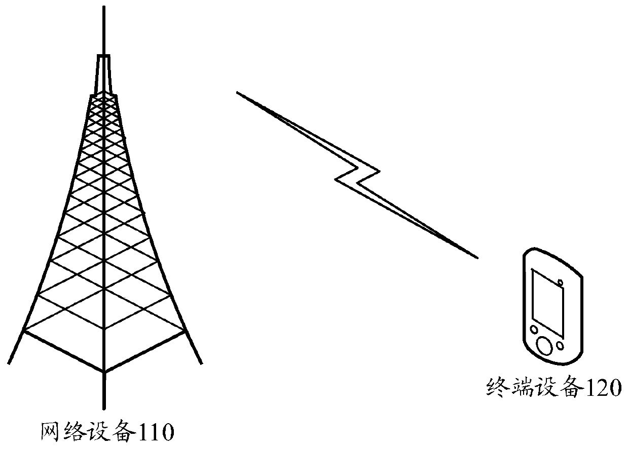
[0066] First, the application scenarios of this application are introduced. figure 1 It is a schematic diagram of a communication system suitable for this application.
[0067] The communication system 100 includes a network device 110 and a terminal device 120 . The terminal device 120 communicates with the network device 110 through electromagnetic waves.
[0068] In this application, the terminal device 120 may include various handheld devices, in-vehicle devices, wearable devices, computing devices, or other processing devices connected to a wireless modem with wireless communication capabilities, for example, the 3rd Generation Partnership Project (3 rd Generation Partnership Project, 3GPP) defined user equipment (user equipment, UE), mobile station (mobile station, MS), soft terminal, home gateway, set-top box, site and so on.
[0069] The network device 110 may be a base station defined by 3GPP, for example, a base station (gNB) in the fifth generation (5G) communication system. The network device 110 may also be a non-3GPP (non-3GPP) access network device, such as an access gateway (access gateway, AGF). The network device 110 may also be a relay station, an access point, an in-vehicle device, a wearable device, and other types of devices.
[0070] The communication system 100 is only an example, and the communication system to which the present application is applied is not limited thereto. For example, the number of network devices and terminal devices included in the communication system 100 may also be other numbers.
[0071] The communication system 100 may be a system using licensed spectrum for communication, or a system using unlicensed spectrum communication, for example, the communication system 100 may be an NR-U system.
[0072] The wireless devices in the NR-U system usually use or share wireless resources by means of channel sensing and contention. Transmitters (gNB or UE) use the same or similar principles to fairly compete for the right to use unlicensed spectrum resources. Generally, the transmitter first monitors whether the unlicensed spectrum is free before sending a signal. For example, the received power on the unlicensed spectrum is used to determine its busy and idle state. If the received power is less than a certain threshold, the unlicensed spectrum is considered to be idle. status, signals can be sent on the unlicensed spectrum, otherwise no signals are sent. This listen-before-send mechanism is called listen-before-talk (LBT).
[0073] Data may be transmitted between the UE and the gNB based on a hybrid automatic repeat request (hybrid automatic repeat request, HARQ) process, and each HARQ process corresponds to a transport block (transport block, TB). If a TB fails to be successfully transmitted during initial transmission, the receiving end may send feedback information to the transmitting end, indicating that the TB has not been successfully received. The transmitting end can retransmit all or part of the content of the TB based on the HARQ process, and the receiving end can combine and process the received multiple data block processes corresponding to the HARQ process to improve the demodulation success rate.
[0074] When communicating based on LBT, the UE cannot always send signals in time due to the uncertainty of the channel occupancy. If the UE fails to give feedback to the gNB in ​​time due to the failure of LBT, the gNB still fails to correctly demodulate the downlink data of the UE, and reschedules the downlink resources to the UE for retransmission, resulting in waste of downlink resources and increased communication delay. big.
[0075] In addition, regardless of whether the communication system 100 is a system using licensed spectrum communication or a system using unlicensed spectrum communication, the network device 110 needs a certain amount of time to demodulate the feedback information. For example, in a 5G communication system, the network device 110 needs about 3 A time slot (slot) is used to demodulate the feedback information, and this demodulation time is also a part of the communication delay.
[0076] In order to reduce the communication delay, the present application provides a method 200 for sending feedback information, and the method 200 can be executed by the terminal device 120. For the sake of brevity, the following terminal devices and network devices are no longer attached with reference numerals. like figure 2 As shown, method 200 includes:
[0077] S210: Receive first downlink control information, where the first downlink control information includes information indicating (or scheduling) the first downlink data, information indicating the first uplink resource, and information indicating the first feedback process. In other words, the first downlink control information includes information for scheduling the first downlink data, information on the first uplink resource, and information on the first feedback process.
[0078] The information indicating the first downlink data is the information required by the terminal device to receive the first downlink data, for example, the time-frequency resources used for transmitting the first downlink data, and the coding and modulation strategy (modulation) used by the first downlink data. and coding scheme, MCS), the HARQ process used by the first downlink data, etc.
[0079] The information indicating the first uplink resource is used to allocate or indicate the first uplink resource, so that the terminal device can use the first uplink resource to send feedback information of the first downlink data. For example, the network device can use the information of the first uplink resource for the terminal The device indicates the time domain location and the frequency domain location corresponding to the first uplink resource.
[0080] The information indicating the first feedback process is used to identify or indicate the first feedback process, so that the terminal device uses the first feedback process to feed back the reception situation of the first downlink data. For example, the information of the first feedback process may be a first physical uplink control channel process identifier (physical uplink control channel process identifier, PUCCH-ID). The information of the first feedback process may further include a first new feedback indicator (new feedback indicator, NFI), and the value of the first NFI is used to indicate the feedback information corresponding to the first PUCCH-ID before the first downlink control information is received Whether the reception is successful, so as to determine whether the first uplink resource needs to be fed back simultaneously with the first feedback information. The NFI may indicate whether only new feedback information (eg, the first feedback information) needs to be fed back on the first uplink resource. If so, it indicates that the previous feedback information was successfully received; if not, it indicates that the previous feedback information was not successfully received. Further, the terminal can learn whether the feedback information corresponding to the first PUCCH-ID is successfully received before receiving the first downlink control information.
[0081] It should be noted that, in the initial transmission, the network device and the terminal device may determine based on a preset rule (for example, a rule defined by a communication protocol or a rule pre-configured by a network device) based on which feedback process to send the feedback of the initial transmission data. In addition, since there is no feedback information of the first downlink data in the initial transmission, the first NFI is meaningless in the initial transmission. Therefore, the first downlink control information may not carry the first PUCCH-ID and the first NFI. Alternatively, the first downlink control information includes the related fields of the first PUCCH-ID and the first NFI, but the fields of these two pieces of information may be set as invalid fields or may be multiplexed with other information.
[0082] The first downlink control information may be downlink control information (downlink control information, DCI). For example, DCI format (format) 1_0 or DCI format 1_1. The first downlink control information including the PUCCH-ID field and the NFI field is shown below.
[0083] The PUCCH-ID field included in DCI format 1_0 and DCI format 1_1 may be x bits, and the NFI field included in DCI format 1_0 and DCI format 1_1 may be y bits. x and y indicate that the present application does not limit the specific number of bits of these two fields. For example, the value of x depends on the number of feedback processes configured by the network device. If the network device is configured with two feedback processes, the value of x may be 1. The value of y can be 1 or other values.
[0084] The cyclic redundancy check (CRC) of DCI format 1_0 and DCI format 1_1 can be identified by a cell radio network temporary identifier (C-RNTI) or a configured scheduled radio network temporary identifier (configured scheduled radio network). network temporary identifier, CS-RNTI) or new RNTI (new-RNTI) scrambling.
[0085] The terminal device receives the first downlink control information. The terminal device receives the first downlink data on the corresponding downlink resource according to the information of the first downlink data. Then, the terminal device feeds back the reception situation of the first downlink data according to the demodulation situation of the first downlink data. That is, the following steps are performed.
[0086] S220: Use the first feedback process to send first feedback information on the first uplink resource, where the first feedback information is used to indicate the reception situation of the first downlink data.
[0087] In the above method, the first downlink data may be one piece of data or multiple pieces of data, and correspondingly, the first feedback information may be one piece of feedback information or multiple pieces of feedback information. Therefore, there is an association relationship between one feedback process and one or more HARQ processes.
[0088] For example, if the network device schedules multiple PDSCHs through multiple DCIs, and these PDSCHs are fed back based on the same PUCCH process, the multiple DCIs indicate the same PUCCH-ID. The PUCCH includes feedback information of multiple PDSCHs. That is to say, multiple PDCCHs schedule multiple PDSCHs, and these PDSCHs use the same PUCCH for feedback and indicate the same PUCCH-ID. This PUCCH will contain ACK and NACK bits of multiple PDSCHs.
[0089] Before sending the first feedback information, the terminal device may determine the association between the first feedback process and the first downlink data according to the first downlink control information, and then determine the association between the first feedback process and the first feedback information .
[0090] Sending the first feedback information by the terminal device using the first feedback process may be understood as: the terminal device records (or stores) the association relationship between the first feedback process and the first feedback information. In this way, after the terminal device sends the first feedback information, the terminal device receives from the network device information including the first feedback process (for example, the first PUCCH-ID). The terminal device determines the reception situation of the first feedback information according to the information including the first feedback process received from the network device. Further, the terminal device also needs the NFI to determine the reception situation of the first feedback information. Optionally, the terminal device may also send the first PUCCH-ID together with the first feedback information to the network device.
[0091] Therefore, S220 can also be replaced by the following description: the first feedback information is sent on the first uplink resource, the first feedback information is used to indicate the reception situation of the first downlink data, and there is a relationship between the first feedback information and the first feedback process connection relation.
[0092]The above association relationship is also stored in the network device. Since different feedback information corresponds to different feedback processes, the network device can schedule the second downlink data without waiting for the demodulation result of the first feedback information after receiving the first feedback information; Alternatively, the network device can schedule the second downlink data transmission without detecting the first feedback information. Thus, the communication delay is reduced.
[0093] In addition, in some communication scenarios, the terminal device will receive two DCIs successively in a short period of time. The two DCIs are, for example, DCI1 and DCI2. DCI1 schedules the first downlink data, DCI2 schedules the second downlink data, and DCI1 is received before DCI2. Since the terminal device has not yet sent the first feedback information when it receives DCI2, DCI2 will carry indication information indicating retransmission of the first feedback information. After the terminal device sends the first feedback information based on DCI1, it will send the first feedback based on DCI2 again. information, resulting in waste of air interface resources.
[0094] After applying method 200, the network device may allocate different feedback processes for the first downlink data and the second downlink data, that is, the first downlink data corresponds to the first feedback process, and the second downlink data corresponds to the second feedback process. When sending the feedback information of the second downlink data, the terminal device does not need to send the first feedback information again if it does not receive the information sent by the network device indicating the failure to receive the first feedback information, thereby reducing the waste of air interface resources.
[0095] In method 200, after the terminal device sends the first feedback information, the network device detects the first feedback information on the first uplink resource. There are two situations in which the network device receives the first feedback information: receiving failure and receiving successfully. The receiving failure may be that the signal carrying the first feedback information is detected, but the demodulation is not successful; the receiving failure may also be that the signal power of the first feedback information is too low, and the network device does not detect the signal carrying the first feedback information; The reception failure may also be a signal that the terminal device does not send the first feedback information due to the LBT failure. Successful reception means that the first feedback information is successfully demodulated. The two cases are described below.
[0096] Case 1: The first feedback information fails to be received or the first feedback information needs to be fed back again.
[0097] In case 1, the network device will send the second DCI to the terminal device, and the second DCI includes the first indication information, which is used to indicate that the first feedback information fails to be received. The first indication information may be the first NFI. The first NFI is used to indicate the reception status of the feedback information corresponding to the first feedback process or whether only the first feedback information needs to be fed back. The first NFI may correspond to or be associated with the first PUCCH-ID. The first PUCCH-ID is used to identify the first feedback process, and the first NFI is used to indicate that the feedback information corresponding to the first PUCCH-ID fails to receive. The first indication information may also be other types of indication information, and this application does not limit the specific form of the first indication information.
[0098] Taking the first indication information as the first NFI and the first PUCCH-ID as an example, after receiving the second DCI, the terminal device can determine whether the network device succeeds based on the predefined rule and the NFI field and the PUCCH-ID field in the first DCI The first feedback information is received or whether the first feedback information needs to be fed back again.
[0099] For example, the predefined rule is: for the same feedback process, if the NFI field in the second DCI is different from the NFI field in the first DCI, it means that the first feedback information is successfully received or the first feedback information does not need to be retransmitted; if The NFI field in the second DCI is the same as the NFI field in the first DCI, which means that the first feedback information fails to be received or the first feedback information needs to be retransmitted. The predefined rule may be a rule defined by a communication protocol or a rule configured by a network device.
[0100] The terminal device determines that the first NFI carried in the first DCI is the same as the second NFI carried in the second DCI, and the first feedback information fails to receive or needs to be fed back again, and then the second uplink resource indicated by the second DCI Send the first feedback information again.
[0101] The above predefined rules are only for illustration, and the predefined rules can also be set as: for the same feedback process, if the NFI field in the second DCI is the same as the NFI field in the first DCI, it means that the first feedback information is successfully received. Or the first feedback information does not need to be retransmitted; if the NFI field in the second DCI is different from the NFI field in the first DCI, it means that the first feedback information fails to be received or the first feedback information needs to be retransmitted. Correspondingly, the NFI field of the second DCI also changes.
[0102] Optionally, the second DCI may further include information of the second downlink data. The information of the second downlink data is used to schedule the terminal device to receive the second downlink data. After receiving the second DCI, the terminal device may use the first feedback process on the second uplink resource to send the first feedback information and the second feedback information, where the second feedback information is used to indicate the reception situation of the second downlink data.
[0103] In case 2, the first feedback information is successfully received or the first feedback information does not need to be retransmitted.
[0104] In case 2, the network device will send a third DCI to the terminal device, where the third DCI includes second indication information, which is used to indicate that the first feedback information is successfully received or the first feedback information does not need to be retransmitted. The second indication information may be the second NFI and the first PUCCH-ID, where the first PUCCH-ID is used to identify the first feedback process, and the second NFI is used to indicate that the feedback information corresponding to the first PUCCH-ID is successfully received or the first A feedback message does not need to be retransmitted. The second indication information may also be other types of indication information, and the present application does not limit the specific form of the second indication information.
[0105] After receiving the third DCI, the terminal device may determine that the first feedback information is successfully received or the first feedback information does not need to be retransmitted based on the predefined rule described in Case 1 and the NFI field and the PUCCH-ID field in the first DCI. Subsequently, the terminal device clears the cache related to the first feedback process, so as to reuse the first feedback process. Correspondingly, after determining that the first feedback information is successfully received, the network device clears the cache related to the first feedback process.
[0106] Optionally, in addition to the second indication information, the third DCI may further include third downlink data information and third uplink resource information. The information of the third downlink data is used to schedule the terminal device to receive the third downlink data, and the information of the third uplink resource is used to allocate or indicate the third uplink resource. After receiving the third DCI, the terminal device may use the first feedback process on the third uplink resource to send third feedback information, where the third feedback information is used to indicate the reception situation of the third downlink data.
[0107] It should be noted that the terminal device may receive the first DCI, the second DCI and the third DCI successively. For example, if the network device successfully demodulates the first feedback information and the second feedback information on the second uplink resource, the network device will send the third DCI after sending the second DCI.
[0108] Further, before sending the first downlink control information, the network device may also send configuration information. The configuration information is used to configure at least two feedback processes, and the at least two feedback processes include the first feedback process. After sending the first downlink control information or after completing the transmission of the first feedback information, the network device may send another downlink control information, and schedule another feedback process for information transmission.
[0109] image 3 An example of the method for sending feedback information provided by this application is shown.
[0110] image 3 In the figure, the shaded part represents DCI, and the physical downlink shared channel (PDSCH) adjacent to each DCI is the downlink data scheduled by the DCI. The terminal device sends feedback information using two PUCCH feedback processes.
[0111] The network device may indicate the PUCCH feedback process number through the PUCCH-ID field with a size of 1 bit in the DCI, where PUCCH-ID=0 identifies feedback process 0, and PUCCH-ID=1 identifies feedback process 1. If the network device has successfully received all previous feedback information of the terminal device, the NFI fields corresponding to PUCCH-ID=0 and PUCCH-ID=1 are both set to "0".
[0112] When scheduling PDSCH#0, the network device instructs the terminal device to use PUCCH feedback process 0 to feed back the feedback information (A/N#0) corresponding to PDSCH#0 on the PUCCH resource through PUCCH-ID=0. When scheduling PDSCH#1, the feedback information (A/N#0) corresponding to PUCCH feedback process 0 has not been processed yet (eg image 3 As shown in the processing delay in ), the network device cannot use the NFI corresponding to PUCCH-ID=0 to indicate the reception of A/N#0. Therefore, the network device will instruct the network device to use PUCCH feedback process 1 to send the feedback information (A/N#1) corresponding to PDSCH#1 through PUCCH-ID=1 in the DCI scheduling PDSCH#1. At this time, the network device does not need to consider whether the network device has successfully received A/N#0. Thus, the scheduling delay of PDSCH#1 is reduced.
[0113] After the network device successfully receives A/N#0, it can reuse the feedback process 0. For example, the network device has completed the processing of the feedback information (A/N#0) corresponding to PUCCH-ID=0 when scheduling PDSCH#2, and correctly received A/N#0 (regardless of A/N#0). ACK or NACK). The network device can reverse the NFI corresponding to the feedback process 0 (set NFI=1), indicating that the terminal device has successfully fed back the feedback of the process 0, and does not need to re-feed back, and at the same time clears all the historical feedback information corresponding to the feedback process 0. Then the buffer storing the HARQ feedback information can be released in time. Optionally, even if the historical cache information corresponding to the feedback process 0 is not cleared, it does not affect the feedback information of continuing to use the feedback process 0 to send new downlink data. At this time, the terminal device needs to send all the stored feedback information together.
[0114] When the network device schedules PDSCH#3, the interval from the time domain position of A/N#1 is greater than the processing delay of the network device. Therefore, the process corresponding to PUCCH-ID=1 has been processed, so the feedback process can continue to be used 1. However, since the network device has not received the relevant A/N#1, the network device needs to instruct the terminal device to continue to use the feedback process 1, while maintaining the state of the NFI corresponding to the previous feedback process 1 (ie, NFI=0), indicating that The terminal device retransmits the feedback information corresponding to the feedback process 1.
[0115] The terminal device may send the feedback information of PDSCH#3 and PDSCH#1 in the same PUCCH, that is, A/N1+3.
[0116] When the terminal device uses the dynamic codebook to feed back the reception of downlink data, the network device may carry a downlink assignment indicator (DAI) in the DCI, and indicate the feedback process corresponding to the DAI to the terminal device.
[0117] For example, when the first DCI includes the first DAI and the first PUCCH-ID, the association relationship between the first DAI and the first feedback process is specified. The second DCI and the third DCI may also carry DAI.
[0118] When the first DCI includes the first DAI, the first DCI may include the parameter The pi in this parameter corresponds to the PUCCH-ID field, and this parameter can be used to identify that the C-DAI corresponds to PUCCH-ID=pi.
[0119] Figure 4 An example of the method for sending feedback information provided by this application is shown.
[0120] When the dynamic codebook is used for feedback, the network device will carry DAI in the DCI, indicating the total number of HARQ processes (that is, the number of all downlink data) that the terminal device needs to feed back by the current scheduling period, and the HARQ scheduled by the current DCI. The number of the process in all HARQ processes that require feedback. When there are multiple feedback processes, the calculation of DAI is only based on the same feedback process.
[0121] Figure 4 , the two shaded rectangles correspond to two feedback processes respectively, PDSCH#0 to PDSCH#2 correspond to feedback process 0 (PUCCH-ID=0), and the feedback information of the three downlink data (A/N#0+1+2 ) on the first PUCCH for feedback. The number of DAI is as shown in the figure, the counter DAI (counter DAI, C-DAI) represents the DAI corresponding to the current PDSCH, and the total DAI (total DAI, T-DAI) represents the current quantity of feedback information to be sent. For example, for PDSCH#0, C-DAI=0 indicates the DAI corresponding to PDSCH#0, and T-DAI=3 indicates that there are currently three pieces of feedback information to be sent, that is, feedback process 0 corresponds to three pieces of feedback information.
[0122] PDSCH#3-6 use feedback process 1 (PUCCH-ID=1), and the feedback information (A/N#3+4+5+6) of the three downlink data is fed back on the second PUCCH. Since different feedback processes are adopted, the numbering of DAI does not need to consider the DAIs of PDSCH#0 to PDSCH#2. Thereby reducing the logic complexity.
[0123] For PDSCH#5 and PDSCH#6, since the feedback processes corresponding to these two PDSCHs are the same as those corresponding to PDSCH#3 and PDSCH#4, the C-DAI and T-DAI of these two PDSCHs are the same as those of PDSCH#3. Related to PDSCH#4. That is, the C-DAI of PDSCH#5 is ordered next to the C-DAI of PDSCH#4, and the C-DAI of PDSCH#6 is ordered next to the C-DAI of PDSCH#5. The T-DAI of PDSCH#5 and PDSCH#6 is equal to the number of all PDSCHs corresponding to the feedback process 1, that is, the T-DAI of PDSCH#5 and PDSCH#6 is equal to 4. That is to say, for multiple PDSCHs with the same feedback process, their respective corresponding C-DAIs can be numbered continuously and T-DAIs can be continuously counted.
[0124] Furthermore, by Figure 4 It can be seen that the network device does not need to wait for A/N#0+1+2 when scheduling PDSCH#3-6, and can directly schedule PDSCH#3-6, thereby reducing the transmission delay of downlink data.
[0125] Due to the uncertainty of the LBT or the instability of the channel, the first feedback information may fail to be received, or not sent successfully, or need to be fed back again. In view of these situations, the present invention also provides a method for sending feedback information. Specifically, the network device may send trigger information to the terminal device. The trigger information is used to instruct the terminal device to carry the first feedback information in the next HARQ feedback. After receiving the trigger information, the terminal device may combine the first feedback information into the second feedback information and send it to the network device.
[0126] When the feedback process corresponding to the first feedback information and the feedback process corresponding to the second feedback information are the same process, HARQ feedback may be performed according to a preset rule. The preset rule may be: when the first feedback information needs to be resent, the first feedback information is carried in the second feedback information by default. The second feedback information may be considered as uplink control information to be performed after the first feedback information. That is to say, because the sending of the previous feedback information fails, the latter feedback information directly includes the previous feedback information by default. At this time, the network device may not send trigger information. The terminal device provides feedback according to preset rules.
[0127] When the feedback process corresponding to the first feedback information and the feedback process corresponding to the second feedback information are the same process, the terminal device determines whether the first feedback information needs to be carried in the next second feedback information according to the trigger information. Further, when the trigger information is the first value, the terminal device carries the first feedback information in the second feedback information. When the trigger information is the second value, the terminal device does not carry the first feedback information in the second feedback information. The trigger information may be 1-bit information.
[0128] Similarly, when both the first feedback information and the second feedback information need to be fed back again, the terminal device may determine whether to carry the first feedback information and/or the second feedback information in the third feedback information according to the trigger information. More scenarios of feedback information can be obtained by referring to the above.
[0129] Optionally, the trigger information may be included in the information indicating the first feedback process, or may be separate indication information, which is not limited in the present invention. For example, the trigger information may be carried in the above second DCI. One bit may be added to the second DCI as the trigger information.
[0130] Optionally, the information indicating the first feedback process sent by the network device may include trigger information (for example, represented by a trigger) to indicate whether the second feedback information and the first feedback information need to be combined. For example, if the trigger field corresponding to the trigger information is "0", it means that merging is not required, and if the field is "1", it means that merging is required. It should be understood that the second feedback information and the first feedback information here are logical distinctions and do not constitute a quantitative limitation. The second feedback information and the first feedback information may respectively correspond to different feedback processes.
[0131] Optionally, the trigger information can be implemented by extending the NFI. For example, NFI is extended from 1 bit to 2 bits. One of the bits implements the existing function of the NFI. For details, refer to the predefined rules in the above case 1. Another bit can be used as trigger information. When the value of the other bit is flipped, it may be considered that the terminal device is instructed to carry the first feedback information in the second feedback information; otherwise, it may be considered that the terminal device is instructed to not carry the first feedback information in the second feedback information.
[0132] Further, when the second feedback information carries the first feedback information, the
[0133] The ACK/NACK can be arranged according to the order of the corresponding feedback processes, or according to the order of HARQ processes, or according to the order of the feedback information that needs to be retransmitted before other feedback information (of course, it can also be reversed). come over). These arrangements are not limited in the embodiments of the present application.
[0134] Figure 4a Another example of the method for sending feedback information provided by this application is shown.
[0135] When the dynamic codebook is used for feedback, the network device will carry DAI in the DCI, indicating the total number of HARQ processes (that is, the number of all downlink data) that the terminal device needs to feed back by the current scheduling period, and the HARQ scheduled by the current DCI. The number of the process in all HARQ processes that require feedback. When there are multiple feedback processes, the calculation of DAI is only based on the same feedback process.
[0136] It can be understood that LBT needs to be performed when the unlicensed spectrum is used for PUCCH transmission. Due to the uncertainty of LBT, the terminal device may not be able to transmit the PUCCH due to LBT failure, or the network device may not be able to correctly receive the PUCCH due to interference problems. .
[0137] Figure 4a , the two shaded rectangles correspond to two feedback processes respectively, PDSCH#0 to PDSCH#2 correspond to feedback process 0 (PUCCH-ID=0), and the feedback information of the three downlink data (A/N#0+1+2 ) on the first PUCCH for feedback. For convenience of description, the feedback information of all downlink data corresponding to the feedback process 0 is referred to as first feedback information. The number of DAI is as shown in the figure, the counter DAI (counter DAI, C-DAI) represents the DAI corresponding to the current PDSCH, and the total DAI (total DAI, T-DAI) represents the number of feedback information that needs to be sent currently. For example, for PDSCH#0, C-DAI=0 indicates the DAI corresponding to PDSCH#0, and T-DAI=3 indicates that there are currently 3 pieces of feedback information to be sent, that is, the first feedback information corresponding to feedback process 0 includes 3 pieces of feedback information. Feedback information (A/N#0+1+2). At this time, the network device indicates the terminal through trigger information (trigger=0), and it is not necessary to combine the feedback information, that is, only the first feedback information needs to be fed back on the first PUCCH.
[0138] PDSCH#3-4 use feedback process 1 (PUCCH-ID=1) to indicate that the feedback information (A/N#3+4) of the two downlink data is fed back on the second PUCCH. The feedback information of all downlink data corresponding to the feedback process 1 is called second feedback information. Since different feedback processes are adopted, the numbering of DAI does not need to consider the DAIs of PDSCH#0 to PDSCH#2. At this time, the second feedback information includes two pieces of feedback information (A/N#3+4), and the network device indicates the terminal through trigger information (trigger=0), and there is no need to combine the feedback information, that is, in the first Only the first feedback information needs to be fed back on the PUCCH.
[0139] For PDSCH#5 and PDSCH#6, the feedback process corresponding to these two PDSCHs may be the same as the feedback process corresponding to PDSCH#3 and PDSCH#4 (PUCCH-ID=1), that is, the feedback information of the four downlink data (A /N#3+4+5+6) feedback on the second PUCCH. Since they belong to the same feedback process, the C-DAI and T-DAI of the two PDSCHs are related to PDSCH#3 and PDSCH#4. That is, the C-DAI of PDSCH#5 is ordered next to the C-DAI of PDSCH#4, and the C-DAI of PDSCH#6 is ordered next to the C-DAI of PDSCH#5. The T-DAI of PDSCH#5 and PDSCH#6 is equal to the number of all PDSCHs corresponding to the feedback process 1, that is, the T-DAI of PDSCH#5 and PDSCH#6 is equal to 4. That is, the second feedback information includes four pieces of feedback information (A/N#3+4+5+6). That is to say, for multiple PDSCHs with the same feedback process, their respective corresponding C-DAIs can be numbered continuously and T-DAIs can be continuously counted.
[0140] Suppose that the terminal device fails to send the first PUCCH successfully due to the LBT failure, in other words, the network device does not correctly receive the first feedback information carried by the first PUCCH. At this time, the network device can instruct the terminal device by triggering information trigger=1. The first feedback information and the second feedback information are sent together on the second PUCCH. by Figure 4a For example, the feedback information of PDSCH #0 to 2 is not successfully transmitted, and according to the trigger information, the terminal sends the feedback information of PDSCH #0 to 6 on the next PUCCH.
[0141] For the terminal device, upon receiving the trigger information trigger=1, it can know that the first feedback information and the second feedback information need to be combined. Therefore, the feedback information of multiple feedback processes is sent together on one PUCCH, which saves overhead.
[0142] Optionally, for PDSCH#5 and PDSCH#6, the feedback process corresponding to these two PDSCHs may be the same as the feedback process corresponding to PDSCH#0 and PDSCH#1 (PUCCH-ID=0). The specific implementation is as follows: Figure 4b As shown, at this time, the first feedback information includes five feedback information (A/N#0+1+2+5+6). In the case that the first feedback information is not successfully transmitted, according to the trigger information, the first feedback information needs to be included in the second feedback information. For example, in Figure 4b, the second feedback information includes the first feedback information and its original information that needs to be fed back (A/N#0+1+2+5+6 and A/N#3+4). Of course, the order of A/N#0+1+2+5+6 and A/N#3+4 can be arbitrary. For example in the order of A/N#0+1+2+5+6+3+4, or in the order of A/N#0+1+2+3+4+5+6 or in the order of A/N#3 The order of +4+0+1+2+5+6.
[0143] It should be understood that, for the initial transmission of the PUCCH, one feedback process in this embodiment of the present application may correspond to one PUCCH. Multiple feedback processes may correspond to multiple PUCCHs, and there is a one-to-one correspondence between them. But optionally, when PUCCH transmission/reception fails, the network device may instruct the terminal device to transmit feedback information of multiple feedback processes on one PUCCH, thereby saving resources, reducing the number of LBTs, and improving efficiency.
[0144] It should also be understood that the feedback process mentioned in the present invention should also be understood as a logical process, which does not mean that the feedback information corresponding to one feedback process can only be transmitted on one fixed PUCCH resource.
[0145] The above mainly describes the method for sending feedback information provided by the present application from the perspective of the terminal device. The processing process of the network device has a corresponding relationship with the processing process of the terminal device. For example, when the terminal device receives information from the network device, it means that the network device sends The information is sent by the terminal device to the network device, which means that the network device receives the information from the terminal device. Therefore, even if the processing procedure of the network device is not clearly stated in individual places above, those skilled in the art can clearly understand the processing procedure of the network device based on the processing procedure of the terminal device.
[0146] Examples of the communication methods provided by the present application are described in detail above. It can be understood that, in order to realize the above-mentioned functions, the communication apparatus includes corresponding hardware structures and/or software modules for executing each function. Those skilled in the art should easily realize that the present application can be implemented in hardware or a combination of hardware and computer software with the units and algorithm steps of each example described in conjunction with the embodiments disclosed herein. Whether a function is performed by hardware or computer software driving hardware depends on the specific application and design constraints of the technical solution. Skilled artisans may implement the described functionality using different methods for each particular application, but such implementations should not be considered beyond the scope of this application.
[0147] The present application may divide the communication device into functional units according to the above method examples. For example, each function may be divided into each functional unit, or two or more functions may be integrated into one processing unit. The above-mentioned integrated units may be implemented in the form of hardware, or may be implemented in the form of software functional units. It should be noted that the division of units in this application is schematic, and is only a logical function division, and other division methods may be used in actual implementation.
[0148] Figure 5 A schematic structural diagram of a communication device provided by the present application is shown. The communication apparatus 500 may be used to implement the methods described in the above method embodiments. The communication apparatus 500 may be a chip, a network device or a terminal device.
[0149] The communication device 500 includes one or more processors 501 that can support the implementation of the communication device 500 figure 2 The method in the corresponding method embodiment. The processor 501 may be a general purpose processor or a special purpose processor. For example, the processor 501 may be a central processing unit (CPU) or a baseband processor. The baseband processor may be used to process communication data (eg, the power saving signal described above), and the CPU may be used to control communication devices (eg, network equipment, terminal equipment, or chips), execute software programs, and process software program data. The communication device 500 may further include a transceiving unit 505 for implementing signal input (reception) and output (transmission).
[0150] For example, the communication apparatus 500 may be a chip, and the transceiver unit 505 may be an input and/or output circuit of the chip, or the transceiver unit 505 may be a communication interface of the chip, and the chip may serve as a terminal device or a network device or other wireless communication components of the device.
[0151] The communication device 500 may include one or more memories 502 on which a program 504 is stored. The program 504 can be executed by the processor 501 to generate instructions 503, so that the processor 501 executes the methods described in the above method embodiments according to the instructions 503. Optionally, data may also be stored in the memory 502 . Optionally, the processor 501 may also read data stored in the memory 502 , the data may be stored at the same storage address as the program 504 , or the data may be stored at a different storage address from the program 504 .
[0152] The processor 501 and the memory 502 may be provided separately, or may be integrated together, for example, integrated on a single board or a system on chip (system on chip, SOC).
[0153] The communication device 500 may further include a transceiver unit 505 and an antenna 506 . The transceiver unit 505 may be called a transceiver, a transceiver circuit or a transceiver, and is used to implement the transceiver function of the communication device through the antenna 506 .
[0154] In a possible design, the processor 501 is configured to execute through the transceiver unit 505 and the antenna 506:
[0155] receiving first downlink control information, where the first downlink control information includes information indicating the first downlink data, information indicating the first uplink resource, and information indicating the first feedback process;
[0156] The first feedback process is used to send first feedback information on the first uplink resource, where the first feedback information is used to indicate the reception situation of the first downlink data.
[0157] In a possible design, the processor 501 is configured to execute through the transceiver unit 505 and the antenna 506:
[0158] sending first downlink control information, where the first downlink control information includes information indicating the first downlink data, information indicating the first uplink resource, and information indicating the first feedback process;
[0159] Detect first feedback information on the first uplink resource, where the first feedback information is used to indicate the reception of the first downlink data, and there is an association relationship between the first feedback information and the first feedback process .
[0160] For a specific manner of receiving or sending power feedback information, reference may be made to the relevant descriptions in the foregoing method embodiments.
[0161] It should be understood that, the steps in the above method embodiments may be implemented by logic circuits in the form of hardware or instructions in the form of software in the processor 501 . The processor 501 may be a CPU, a digital signal processor (digital signal processor, DSP), an application specific integrated circuit (application specific integrated circuit, ASIC), a field programmable gate array (field programmable gate array, FPGA) or other programmable logic devices, For example, discrete gates, transistor logic devices, or discrete hardware components.
[0162] The present application also provides a computer program product, which, when executed by the processor 501, implements the communication method described in any of the method embodiments in the present application.
[0163] The computer program product can be stored in the memory 502 , such as a program 504 , and the program 504 is finally converted into an executable object file that can be executed by the processor 501 through processing processes such as preprocessing, compilation, assembly, and linking.
[0164] The present application also provides a computer-readable storage medium on which a computer program is stored, and when the computer program is executed by a computer, implements the communication method described in any method embodiment in the present application. The computer program can be a high-level language program or an executable object program.
[0165] The computer-readable storage medium is, for example, the memory 502 . Memory 502 may be volatile memory or non-volatile memory, or memory 502 may include both volatile memory and non-volatile memory. The non-volatile memory may be read-only memory (ROM), programmable read-only memory (PROM), erasable programmable read-only memory (EPROM), electrically erasable memory Except programmable read-only memory (electrically EPROM, EEPROM) or flash memory. Volatile memory may be random access memory (RAM), which acts as an external cache. By way of example and not limitation, many forms of RAM are available, such as static random access memory (SRAM), dynamic random access memory (DRAM), synchronous dynamic random access memory (SDRAM) ), double data rate synchronous dynamic random access memory (double data rate SDRAM, DDR SDRAM), enhanced synchronous dynamic random access memory (enhanced SDRAM, ESDRAM), synchronous link dynamic random access memory (synchlink DRAM, SLDRAM) And direct memory bus random access memory (direct rambus RAM, DR RAM).
[0166] When the communication device 500 is a terminal device, Image 6 A schematic structural diagram of a terminal device provided by the present application is shown. The terminal device 600 can be adapted to figure 1 In the system shown, the functions of the terminal device in the above method embodiments are implemented. For ease of explanation, Image 6 Only the main components of the terminal device are shown.
[0167] like Image 6 As shown, the terminal device 600 includes a processor, a memory, a control circuit, an antenna, and an input and output device. The processor is mainly used to process communication protocols and communication data, and to control the entire terminal device. For example, the processor receives power saving signals through the antenna and control circuitry. The memory is mainly used to store programs and data, such as communication protocols and data to be sent. The control circuit is mainly used for the conversion of the baseband signal and the radio frequency signal and the processing of the radio frequency signal. The control circuit together with the antenna can also be called a transceiver, which is mainly used to send and receive radio frequency signals in the form of electromagnetic waves. The input and output device is, for example, a touch screen or a keyboard, which is mainly used for receiving data input by the user and outputting data to the user.
[0168] When the terminal device is powered on, the processor can read the program in the memory, interpret and execute the instructions contained in the program, and process the data in the program. When it is necessary to send information through the antenna, the processor performs baseband processing on the information to be sent, and outputs the baseband signal to the radio frequency circuit. Send out. When the electromagnetic wave (ie, radio frequency signal) carrying information reaches the terminal device, the radio frequency circuit receives the radio frequency signal through the antenna, converts the radio frequency signal into a baseband signal, and outputs the baseband signal to the processor, which converts the baseband signal into information and process the information.
[0169] Those skilled in the art can understand that, for the convenience of description, Image 6Only one memory and one processor are shown. In an actual terminal device, there may be multiple processors and multiple memories. The memory may also be referred to as a storage medium or a storage device, etc., which is not limited in this application.
[0170] As an optional implementation, Image 6 The processor in can integrate the functions of the baseband processor and the CPU, and those skilled in the art can understand that the baseband processor and the CPU can also be independent processors, interconnected by technologies such as a bus. Those skilled in the art can understand that a terminal device may include multiple baseband processors to adapt to different network standards, a terminal device may include multiple CPUs to enhance its processing capability, and various components of the terminal device may be connected through various buses. The baseband processor may also be referred to as a baseband processing circuit or a baseband processing chip. A CPU may also be referred to as a central processing circuit or a central processing chip. The function of processing the communication protocol and communication data may be built in the processor, or may be stored in the memory in the form of a program, and the processor executes the program in the memory to realize the baseband processing function.
[0171] In this application, an antenna and a control circuit with a transceiving function can be regarded as the transceiver 601 of the terminal device 600, which is used to support the terminal device to implement the receiving function in the method embodiment, or is used to support the terminal device to implement the method embodiment. send function in . The processor having the processing function is regarded as the processor 602 of the terminal device 600 . like Image 6 As shown, the terminal device 600 includes a transceiver 601 and a processor 602 . A transceiver may also be referred to as a transceiver, a transceiver, or the like. Optionally, the device for implementing the receiving function in the transceiver 601 may be regarded as a receiver, and the device for implementing the transmitting function in the transceiver unit 601 may be regarded as a transmitter. That is, the transceiver 601 includes a receiver and a transmitter, the receiver may also be referred to as a receiver, an input port, a receiving circuit, etc., and the transmitter may be referred to as a transmitter, an output port, a transmitting circuit, and the like.
[0172] The processor 602 may be configured to execute a program stored in the memory to control the transceiver unit 601 to receive signals and/or transmit signals, so as to complete the functions of the terminal device in the above method embodiments. As an implementation manner, the function of the transceiver unit 601 can be considered to be implemented by a transceiver circuit or a dedicated transceiver chip.
[0173] When the communication device 500 is a network device, Figure 7 It is a schematic structural diagram of a network device provided by the present application, and the network device may be, for example, a base station. like Figure 7 As shown, the base station can be applied as figure 1 In the shown system, the functions of the network device in the above method embodiments are implemented. The base station 700 may include one or more radio frequency units, such as a remote radio unit (remote radio unit, RRU) 701 and at least one baseband unit (baseband unit, BBU) 702 . The BBU 702 may include a distributed unit (distributed unit, DU), and may also include a DU and a centralized unit (central unit, CU).
[0174] The RRU 701 may be referred to as a transceiver unit, a transceiver, a transceiver circuit or a transceiver, and it may include at least one antenna 7011 and a radio frequency unit 7012 . The RRU701 is mainly used for sending and receiving radio frequency signals and converting radio frequency signals to baseband signals, for example, for supporting the base station to implement the sending function and the receiving function in the method embodiment. The BBU702 is mainly used to perform baseband processing and control the base station. The RRU 701 and the BBU 702 may be physically set together, or may be physically separated, that is, a distributed base station.
[0175] The BBU702 can also be called a processing unit, and is mainly used to complete baseband processing functions, such as channel coding, multiplexing, modulation, spectrum spreading, and so on. For example, the BBU 702 may be used to control the base station to perform the operation procedures related to the network device in the foregoing method embodiments.
[0176] The BBU702 can be composed of one or more boards, and multiple boards can jointly support a wireless access network with a single access standard (for example, a long term evolution (LTE) network), or can support different access standards respectively. wireless access network (such as LTE network and NR network). The BBU 702 also includes a memory 7021 and a processor 7022, and the memory 7021 is used to store necessary instructions and data. For example, the memory 7021 stores the power consumption saving signal in the above method embodiments. The processor 7022 is configured to control the base station to perform necessary actions, for example, to control the base station to perform the operation procedures in the foregoing method embodiments. Memory 7021 and processor 7022 may serve one or more single boards. That is to say, the memory and processor can be provided separately on each single board. It can also be that multiple boards share the same memory and processor. In addition, necessary circuits may also be provided on each single board.
[0177] It should be noted, Figure 7 The shown base station is just an example, and the network device applicable to the present application may also be an active antenna unit (active antenna unit, AAU) in an active antenna system (active antenna system, AAS).
[0178] Those skilled in the art can clearly understand that, for the convenience and brevity of description, for the specific working process of the above-described systems, devices and units, reference may be made to the corresponding processes in the foregoing method embodiments, which will not be repeated here.
[0179] In the several embodiments provided in this application, the disclosed systems, devices and methods may be implemented in other manners. For example, some features of the method embodiments described above may be omitted, or not implemented. The apparatus embodiments described above are only illustrative, and the division of units is only a logical function division. In actual implementation, there may be other division methods, and multiple units or components may be combined or integrated into another system. In addition, the coupling between the various units or the coupling between the various components may be direct coupling or indirect coupling, and the above-mentioned coupling includes electrical, mechanical or other forms of connection.
[0180] It should be understood that, in the various embodiments of the present application, the size of the sequence numbers of each process does not mean the sequence of execution, and the execution sequence of each process should be determined by its functions and inherent logic, rather than the embodiments of the present application. implementation constitutes any limitation.
[0181] Additionally, the terms "system" and "network" are often used interchangeably herein. The term "and/or" in this article is only an association relationship to describe the associated objects, indicating that there can be three kinds of relationships, for example, A and/or B, it can mean that A exists alone, A and B exist at the same time, independently There are three cases of B. In addition, the character "/" in this document generally indicates that the related objects are an "or" relationship.
[0182] In a word, the above descriptions are only preferred embodiments of the technical solutions of the present application, and are not intended to limit the protection scope of the present application. Any modification, equivalent replacement, improvement, etc. made within the spirit and principle of this application shall be included within the protection scope of this application.

PUM

no PUM

Description & Claims & Application Information

We can also present the details of the Description, Claims and Application information to help users get a comprehensive understanding of the technical details of the patent, such as background art, summary of invention, brief description of drawings, description of embodiments, and other original content. On the other hand, users can also determine the specific scope of protection of the technology through the list of claims; as well as understand the changes in the life cycle of the technology with the presentation of the patent timeline. Login to view more.

Similar technology patents

Beam failure processing method, terminal and network equipment

PendingCN114501506ASolve poor communication performanceReduce transmission delay
Owner:DATANG MOBILE COMM EQUIP CO LTD

Method, device and computer-readable storage medium for relay transmission

ActiveCN108521851BReduce processing complexityReduce transmission delay
Owner:GUANGDONG OPPO MOBILE TELECOMM CORP LTD

Message recombination method and network equipment

PendingCN111371703AImprove recombination efficiencyReduce transmission delay
Owner:MAIPU COMM TECH CO LTD

Real-time remote driving system and method

Owner:HUMAN HORIZONS (SHANGHAI) AUTONOMOUS TECH CO LTD

D trigger structure with asynchronous setting reset and rapid output

PendingCN111641403AReduce transmission delayReduce Logic Latency
Owner:南开大学深圳研究院 +1

Classification and recommendation of technical efficacy words

Why Eureka
Try Eureka