A vortex control cavitation device for reducing drag in the air layer of a ship

A technology of cavitation and air layer, which is applied in the direction of hull, ship construction, hull design, etc., can solve the problems that the air layer at the bottom of the ship is difficult to maintain for a long time, the air layer at the bottom of the ship loses its drag reduction ability, and cannot achieve the expected effect, etc., to achieve Reduced energy consumption, reduced wetted surface area, and compact structure

Active Publication Date: 2021-01-29
CHINA SHIP SCIENTIFIC RESEARCH CENTER (THE 702 INSTITUTE OF CHINA SHIPBUILDING INDUSTRY CORPORATION)
View PDF11 Cites 0 Cited by
  • Summary
  • Abstract
  • Description
  • Claims
  • Application Information

AI Technical Summary

Problems solved by technology

[0003] At present, because the vortex system inside the cavitation will interfere with the air layer at the bottom of the ship, it is difficult to maintain the air layer at the bottom of the ship for a long time, resulting in the loss of the drag reduction ability of the air layer at the bottom of the ship, making this technology unable to achieve the expected effect in the application process

Method used


Image

  • A vortex control cavitation device for reducing drag in the air layer of a ship
  • A vortex control cavitation device for reducing drag in the air layer of a ship
  • A vortex control cavitation device for reducing drag in the air layer of a ship

Examples


Embodiment Construction

[0021] The specific implementation manner of the present invention will be described below in conjunction with the accompanying drawings.

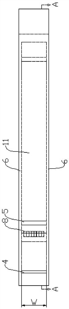
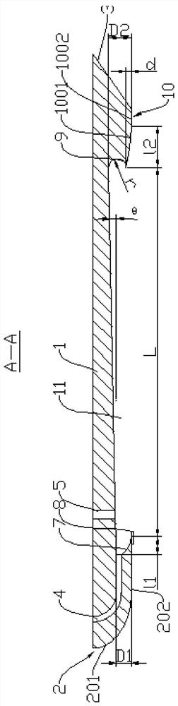
[0022] Such as figure 1 and 2 As shown, the present invention mainly includes a cavitation body 1, and the lower end surface of the cavitation body 1 is provided with an air cavity 11 capable of forming a drag-reducing air layer. The left and right sides of the cavitation body 1 are respectively provided with gas collecting plates 6 , and the height dimension of the gas collecting plate 6 is the same as the depth dimension of the air cavity 11 .

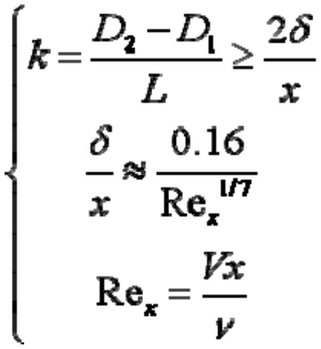
[0023] Such as figure 2 As shown, the air pocket 11 is a non-equal depth air pocket, and the distance from the top surface of the air pocket 11 to the bottom end surface changes from small to large from the front of the air pocket 11 to the rear of the air pocket 11, increasing from D1 to D2, and the non-equal depth air pocket The slope satisfies the following formula relationship:

[0024] ...


PUM


Abstract

The invention relates to the technical field of ship drag reduction, in particular to a vortex-controlled cavitation device for ship air layer drag reduction. It includes a cavitation body, the lower end surface of the cavitation body is provided with a cavitation, and the vertical inner wall of the front part of the cavitation body is provided with an arc-shaped front stabilizing vortex end surface, and the front stabilizing vortex end surface and the top of the cavitation body A leading edge cavity is formed between the inner wall surfaces; the front part of the cavitation body is provided with a front diversion end surface, and the rear end of the front diversion end surface is fixed with a plurality of large eddy breakers, and a part of the plates of the plurality of large vortex breakers The body is suspended at the opening of the air pocket. In the present invention, a large vortex breaker is arranged in parallel on the front diversion end face, and the large vortex breaker can weaken the interaction between the free shear layer above the opening of the cavitation and the vortex system inside the cavitation, so that the air layer exists stably at the bottom of the cavitation.

Description

technical field [0001] The invention relates to the technical field of ship drag reduction, in particular to a vortex-controlled cavitation device for ship air layer drag reduction. Background technique [0002] The gas lubrication drag reduction technology on the hull surface is to inject an appropriate amount of gas into the bottom of the ship through the gas drag reduction device, form and maintain a thin air layer on the bottom of the ship, effectively separate the bottom of the ship from the water, reduce the wet surface area of ​​the bottom of the ship, and significantly reduce the resistance of the ship An energy saving technology. [0003] At present, the vortex system inside the cavitation will interfere with the air layer at the bottom of the ship, making it difficult to maintain the air layer at the bottom of the ship for a long time, resulting in the loss of drag reduction ability of the air layer at the bottom of the ship, making this technology unable to achiev...

Claims


Application Information

Patent Timeline
Patent Type & Authority Patents(China)
IPC IPC(8): B63B1/38
CPCB63B1/38B63B2001/387Y02T70/10
Inventor 刘建华高丽瑾
Owner CHINA SHIP SCIENTIFIC RESEARCH CENTER (THE 702 INSTITUTE OF CHINA SHIPBUILDING INDUSTRY CORPORATION)
Why Eureka
Try Eureka