Cable take-up and pay-off device capable of compressing cable for communication engineering

A technology of communication engineering and retractable device, applied in the field of communication engineering, can solve the problems of loose cable winding, falling off of the winding device, difficult communication engineering, etc., to ensure the efficiency of retraction and deployment, prevent fluffy, and have strong practicability Effect

Inactive Publication Date: 2020-08-28
纪建德
View PDF1 Cites 9 Cited by
  • Summary
  • Abstract
  • Description
  • Claims
  • Application Information

AI Technical Summary

Problems solved by technology

[0002] In the process of communication engineering construction, it is usually necessary to use long communication cables to monitor signals and data, and the cables usually need to be wound before use, because the existing winding and winding equipment is in use There is no necessary pressing device in the process, so that the cable is easy to loosen when it is rolled up, and it is easy to fall off from the winding device, which is not easy to carry out communication engineering construction.
[0003] The Chinese patent (Notice No. CN 210312969 U) discloses a retracting device for communication equipment cables. Through the setting of the rotating plate, limit rod and winding roller, the communication cables can be better wound up and avoid retraction. When the winding roller rotates, it is preliminarily guaranteed that the cable can be in a stable state when it is in the winding state; through the adjustment device, the Z-shaped pressure rod, the connection block and the setting of the screw, the Z-shaped pressure rod can be placed between the first fixed plate and the first fixed plate. The second fixing plate is vertically lowered, so that the cables wound on the outside thereof are compressed and fixed, and the occurrence of looseness is avoided. Although the structure of the device can realize the compression and fixation of the cables, its It is fixed after the cable winding is completed, and in the process of cable winding, the cable will be lifted due to various reasons, making the cable winding relatively fluffy, affecting the quality of winding and unwinding s efficiency

Method used


Image

  • Cable take-up and pay-off device capable of compressing cable for communication engineering
  • Cable take-up and pay-off device capable of compressing cable for communication engineering
  • Cable take-up and pay-off device capable of compressing cable for communication engineering

Examples


Embodiment 1

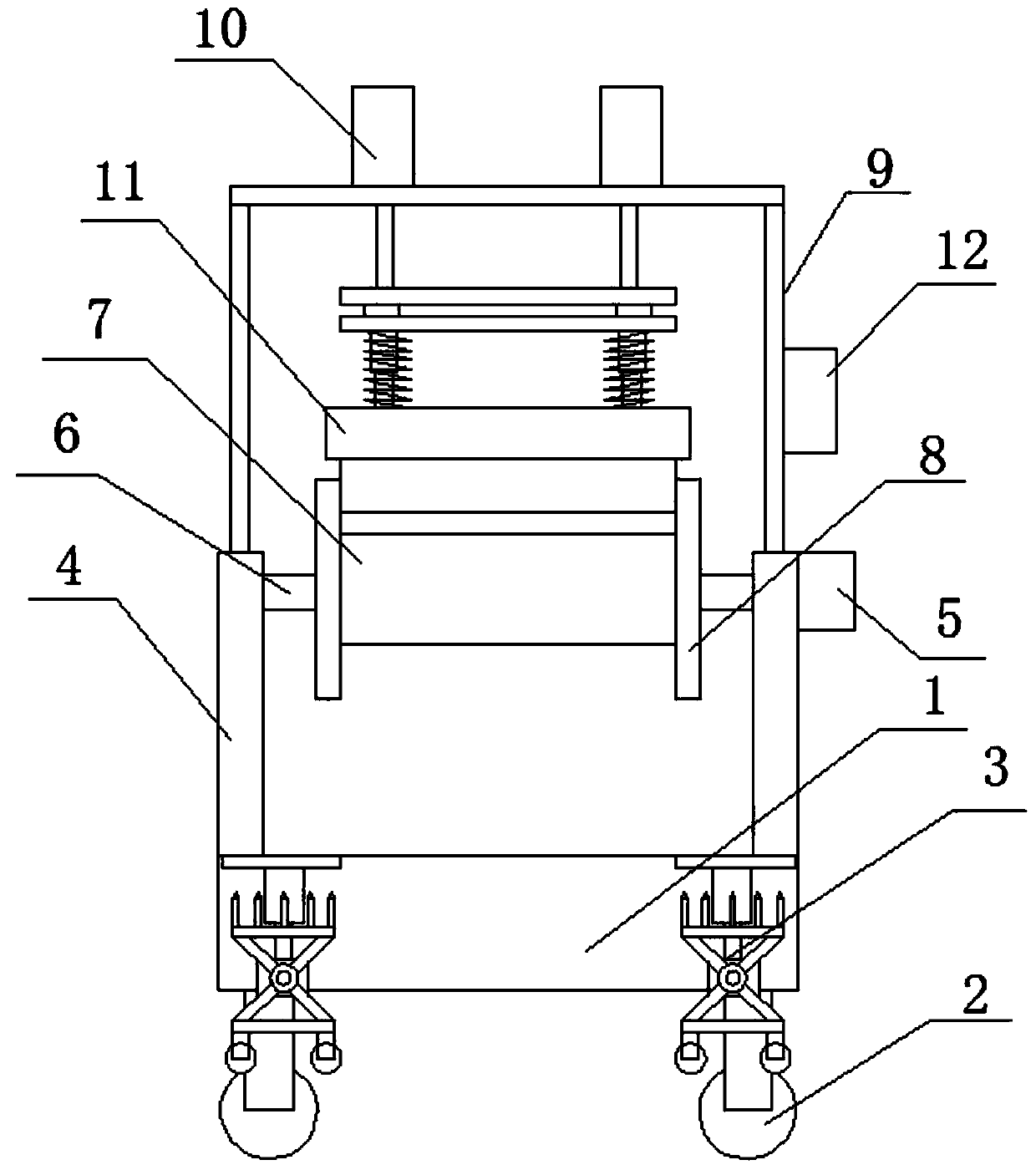
[0022] see Figure 1-4 , in an embodiment of the present invention, a cable retracting device for communication engineering, which can compress cables, includes a base 1, and the four corners of the lower side of the base 1 are provided with universal wheels 2, and the upper side of the base 1 is left and right symmetrical. A vertical plate 4 is provided, and a drive motor 5 is provided at the upper end of the vertical plate 4 on the left side, and a drive shaft 6 is provided at the output end of the drive motor 5, and a winding roller 7 is arranged on the drive shaft 6, and the winding line The left and right ends of the roller 7 are provided with a limiting plate 8, and the upper end of the vertical plate 4 is provided with a mounting frame 9, and the left and right symmetrically arranged on the mounting frame 9 is provided with a first electric telescopic mechanism 10, and the first electric telescopic mechanism The lower end of 10 is provided with pressing mechanism 11, an...

Embodiment 2

[0025] On the basis of Embodiment 1, the front and rear sides of the base 1 are symmetrically provided with a positioning mechanism 3, the positioning mechanism 3 includes a mounting plate 22 connected to the base 1, and the lower side of the mounting plate 22 is installed There is a second electric telescopic mechanism 23, the lower end of the second electric telescopic mechanism 23 is provided with a support base 24, the front side of the support base 24 is provided with a rotating column 25, and a rotating sleeve 26 is installed on the rotating column 25, The outer side of the rotating sleeve 26 is provided with four support rods 27 at equal angles, and the outer ends of the two support rods 27 below are provided with a first fixed plate 28, and the lower side of the first fixed plate 28 is provided with a number of spare wheels. 29 , the outer ends of the upper two supporting rods 27 are provided with a second fixing plate 30 , and the upper side of the second fixing plate ...


PUM


Abstract

The invention relates to the field of communication engineering, in particular to a cable take-up and pay-off device capable of compressing a cable for communication engineering. The cable take-up andpay-off device comprises a base, a mounting frame is arranged at the upper end of a vertical plate, first electric telescopic mechanisms are bilaterally symmetrically arranged on the mounting frame,and compressing mechanisms are arranged at the lower ends of the first electric telescopic mechanisms; and each compressing mechanism comprises a connecting plate connected with the lower end of the corresponding first electric telescopic mechanism, a pressure sensor is arranged on the lower side of each connecting plate, a supporting plate is arranged at the lower end of each pressure sensor, telescopic rods are arranged on the lower side of the supporting plate in a bilateral symmetry mode, springs are arranged on the outer sides of the telescopic rods, pressing seats are arranged at the lower ends of the telescopic rods, a cavity is formed in the lower side of each pressing seat, and a pressing roller is connected into each cavity through a rotating shaft. By means of the structural arrangement of the device, the cable can be compressed in real time when the cable is wound and unwound, the cable is prevented from being wound loosely, and the cable winding and unwinding quality and winding and unwinding efficiency are guaranteed.

Description

technical field [0001] The invention relates to the field of communication engineering, in particular to a cable retracting device for communication engineering that can compress cables. Background technique [0002] In the process of communication engineering construction, it is usually necessary to use long communication cables to monitor signals and data, and the cables usually need to be wound before use, because the existing winding and winding equipment is in use During the process, there is no necessary pressing device, so that the cable is easy to loosen when it is rolled up, and then it is easy to fall off from the winding device, which is not easy to carry out the communication engineering construction. [0003] The Chinese patent (Notice No. CN 210312969 U) discloses a retracting device for communication equipment cables. Through the setting of the rotating plate, limit rod and winding roller, the communication cables can be better wound up and avoid retraction. ...

Claims


Application Information

Patent Timeline
Patent Type & Authority Applications(China)
IPC IPC(8): B65H75/40B65H75/44
CPCB65H75/40B65H75/44B65H2701/34
Inventor 纪建德
Owner 纪建德
Why Eureka
Try Eureka